This guide outlines the recommended steps for preparing and configuring Cisco for integration with NiCE CXone Real-Time Third Party Telephony Recording (Multi-ACD). The procedures described in this guide are not intended to replace official Cisco documentation. A Cisco site engineer should perform the CUCM![]() Cisco Unified Communications Manager. Software-based call-processing component of the Cisco IP telephony solution. configuration.
Cisco Unified Communications Manager. Software-based call-processing component of the Cisco IP telephony solution. configuration.
Use this workflow to configure the integration with Real-Time Third Party Telephony Recording (Multi-ACD) using:
-
CUCM (Cisco Unified Communications Manager) with JTAPI active recording and a Network Based Recording (NBR) method
-
CUBE (Cisco Unified Border Element) or vCUBE (Virtual Cisco Unified Border Element)
-
AudioCodes SBC
-
Oracle (Acme Packet) SBC
-
Ribbon (Sonus) SBC
Phase 1: Prepare Information for NiCE Professional Services
Phase 2: Prepare CUCM Environment
-
Step 1: Configure an Application User
-
Step 2: Configure Device Association
-
Step 3: Configure Extension Mobility
Phase 3: Configure Additional SBC as SIP and Media Proxy by preparing one of these SBCs:
Phase 4: Configure Network Based Recording (NBR) with Additional SBC
-
Step 1: Configure a SIP Profile
-
Step 2: Configure a SIP Trunk
-
Step 3: Configure a Recording Profile
-
Step 4: Configure a Route Group
-
Step 5: Configure a New Route List
-
Step 6: Configure a New Route Pattern
-
Step 8: Associate Recording Profile
Use Prepare Information for NiCE Professional Services and the Essential Data for 3rd Party Connectivity Config in NiCE CXone Excel file to record and save all parameters. You will be required to fill in essential information as you proceed. Once you have finished entering all the necessary details and prepared your environment for Real-Time Third Party Telephony Recording (Multi-ACD), you must submit the Excel file to your NiCE Professional Services representative.
Prepare Information for NiCE Professional Services
CUCM Information Required for Real-Time Third Party Telephony Recording (Multi-ACD)
Before the NiCE Professional Services representative can begin the CTI integration, they require specific information from you. Verify that you provide all relevant information.
|
parameter |
Where is this configured? |
value |
|---|---|---|
|
User ID (Application User) |
Configured in the CUCM > User Management > Application User. |
nicecti |
| Password for User ID | Configured in the CUCM > User Management > Application User. | |
| Associating the devices | Ensure that the recorded phones are associated with the nicecti user. | |
| CUCM IP address |
Public IP address or NAT’d IP address of the CUCM CTI service. |
|
| Secondary CUCM IP address |
Secondary Public IP address or NAT’d IP address of the CUCM CTI service. The NiCE CXone's best practice is to use this. It is required when configuring UCCE as a secondary link. |
|
| List of extensions to be monitored |
List of extensions to be monitored. For JTAPI integrations include:
|
|
|
What Notification Tone levels have been defined? |
If you require Playtone, has the Cisco site engineer configured the Notification Tones on the relevant level: system-wide or device level? |
AudioCodes or CUBE SBC Information Required for Real-Time Third Party Telephony Recording (Multi-ACD)
|
parameter |
comments |
|---|---|
|
SBC Public IP |
Public IP of external SBC SIP interface |
| SBC Certificate Authority (CA) Certificate | CA or self-signed certificate of SBC |
UCCE Information Required for Real-Time Third Party Telephony Recording (Multi-ACD)
The NiCE Professional Services representative requires this information for CTI configuration if UCCE is being used as a secondary link or as a CTI Interface. Verify that you provide all relevant information.
|
parameter |
Where is this configured? |
value |
|---|---|---|
|
CG - Primary |
Parameters configured in the Client Gateway (CG):
|
|
|
CG - Secondary |
(Optional) Provide the above information also for the Secondaryserver:
|
|
| Devices configured in the End User |
Go to CUCM > User Management > End User. Verify the list of configured devices. |
|
| List of site-specific CallVariables, ECC variables / arrays business data fields |
Include their exact names and their sizes. |
|
| List of all agents |
Include a list of Agent IDs. |
Information You Need
Verify the following before the NiCE Professional Services representative begins configuration:
-
For JTAPI business data:
-
If the site requires CurrentCalledName, or CurrentCallingName, verify that the Display Internal Caller field has been configured.
-
If the site requires CalledName information, verify that the Alerting Name
 The caller’s name displayed on the phone during incoming calls. May indicate if the call is internal or external when the phone is answered. field has been configured.
-
-
Complete list of devices needed for both monitoring purposes.
-
Does the CUCM site configuration use extension mobility
Extension Mobility allows users to configure a device as their own, on a temporary basis, by logging into that phone. Once a user logs in, the device adopts the user’s individual user device profile information, including their line numbers, speed dials, services links, and other user-specific properties of a phone.
A user can be logged in to numerous devices at the same time.
When Extension Mobility is configured for the Multiple Login Allowed, a user can be logged in to numerous devices at the same time and have simultaneous calls on all of them., shared lines A Shared Line is a DN that appears on more than one device in the same partition.
Incoming calls display on all devices that share a line and anyone can answer the call.
Multiple calls can take place at the same time, either on the same device or on multiple devices.
For example, you can set up a shared line, so a directory number appears on line 1 of a manager phone and also on line 1 of an assistant phone. Another example of a shared line involves a single incoming 800 number that is set up to appear as line 2 on every sales representative phone in an office.
Shared Lines are an important factor to consider for system mapping., or multiple lines? Provide all relevant device configuration information.
Create a Secure CTI Connection Using VPN
This step must be performed only in coordination with NiCE Professional Services.
At the end this step, by completing the VPN form, you will provide the necessary details to NiCE Professional Services, who will aid you in establishing a secure VPN connection with NiCE CXone.
-
NiCE Professional Services will provide you with the VPN connect form.
-
Fill out the provided form with details of your side and the necessary information for Real-Time Third Party Telephony Recording (Multi-ACD).
-
NiCE Professional Services will coordinate with NiCE CXone teams to ensure all fields are appropriately filled out.
-
Both parties must agree on the form and details.
-
-
NiCE Professional Services will schedule a collaborative call:
- To agree on the form and provided details with Real-Time Third Party Telephony Recording (Multi-ACD).
-
With NiCE CXone teams for VPN provisioning.
-
You will set up two VPNs: one for resiliency and one for failover.
-
Configure routing by setting up BGP over VPN with Real-Time Third Party Telephony Recording (Multi-ACD) firewalls or create static routes to the provided IP addresses.
-
Configure NAT. NAT your endpoint behind a public IP, either advertised via BGP or using static routing.
-
Configure firewall settings:
-
Allow inbound traffic from the provided IP addresses (2) into the CTI Endpoint.
-
Open the required ports. See Ports and Protocols by Application for more information.
-
For High Availability environments, the ports mentioned above in step b must be open for all servers, active and standby.
-
-
NiCE Professional Services will coordinate with NiCE CXone teams to:
-
Ensure the VPN form is correctly filled out.
-
Schedule a time with NiCE CXone teams for VPN provisioning and routing setup.
-
Test VPN tunnel, routing, and connectivity.
-
Prepare CUCM Environment
Prepare the CUCM environment for Cisco’s integration with Real-Time Third Party Telephony Recording (Multi-ACD). This section describes procedures for preparing the CUCM versions 12.5, 14 and 15.
The actual switch configuration is performed by the Cisco site engineer only.
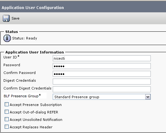
Configure an Application User
Configure the Application user as nicecti user. The nicecti user communicates between the CUCM and JTAPI client on Real-Time Third Party Telephony Recording (Multi-ACD).
At the end of this step, you are required to provide to NiCE Professional Services:
-
User ID
-
Password
-
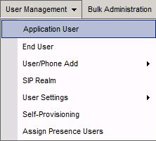
In the CUCM Administration application, go to User Management > Application User.
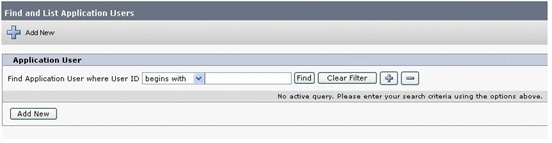
The Find and List Application Users window appears.
-
Click Add New.
-
In the Application User Information area:
-
Enter nicecti for User ID.
-
Enter the password in the Password field.
-
Enter the same password in the Confirm Password field.
-
-
Write down the correct User ID that you created and its password. The NiCE Professional Services representative will require this information for configuration.
-
Click Save.
-
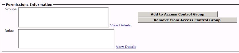
Scroll down to the Permissions Information area.
-
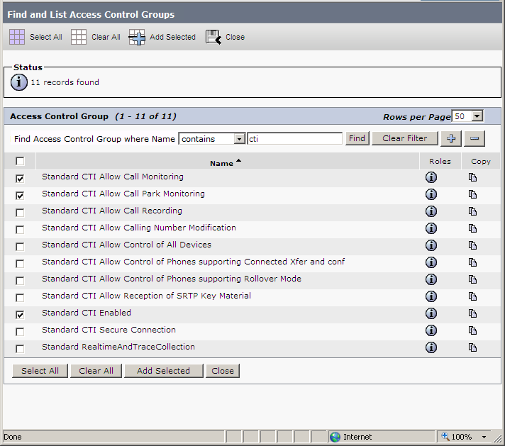
Click Add to Access Control Group.
-
In the Find and List Access Control Groups window, define a search for a User group:
-
From the Find Access Control Group where Name drop-down list, select contains.
-
In the empty field, enter cti.
-
Click Find.
-
-
Select the access control groups:
-
For all integrations: Standard CTI Allow Call Monitoring and Standard CTI Allow Call Recording
-
For Cisco JTAPI Active: Standard CTI Enabled (for both secured and non-secured connection configurations)
-
To monitor Call Parks: Standard CTI Allow Call Park Monitoring
-
To monitor 88XX, 89XX, and 99XX phone series: Standard CTI Allow Call Control of Phones supporting Connected Xfer and conf.
-
To enable 88XX, 89XX, and 99XX phone series: Standard CTI Allow Control of Phones supporting Rollover Mode
Device monitoring of 88xx, 89XX, and 99xx devices will fail if the Standard CTI Allow Control of Phones supporting Connected Xfer and conf group is not added.
-
-
Verify that you selected each group for your configuration. Click Add Selected.
-
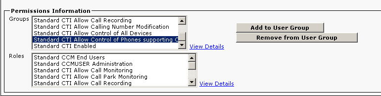
In the Application User Configuration window, click Save.
-
In the Permissions Information area, verify that all roles are associated with each user group.
-
Standard CTI Allow Call Control of Phones supporting Connected Xfer and conf only appears if added.
-
If required, ensure that Standard CTI Allow Call Park Monitoring appears.
-
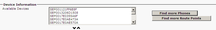
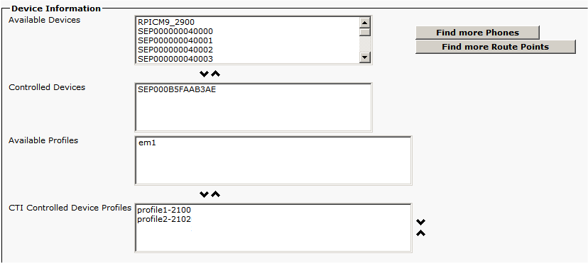
Configure Device Association
Define all devices (the hard phones and softphones) requiring recording as monitored devices. Associate the monitored devices with this new user (nicecti).
-
Verify that the Application User was configured.
-
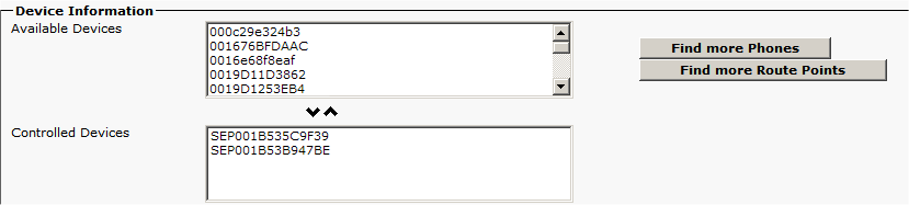
In the Application User Configuration window, scroll down to the Device Associations area and then to the Device Information area.
-
Click Find more Phones.
-
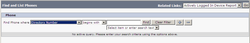
In the Find and List Phones window, in the Phone area, from the Find Phone where drop-down list, select Directory Number.
-
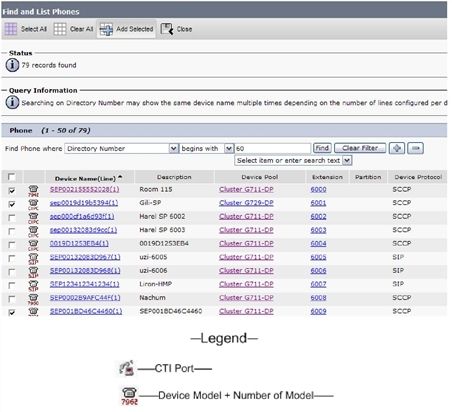
Click Find to search for devices that need monitoring:
Do not associate Voice mail ports or Route Patterns.
-
-
Select the devices: extensions.
-
Click Add Selected.
-
Click Save.
Configure Extension Mobility
-
Verify that the device association was configured.
-
In the Application User Configuration window, scroll down to the Device Information area. All extension mobility profiles appear in the Available Profiles list.
-
Select the extension mobility profile, click the arrow to move it to the CTI Controlled Device Profiles list.
-
Verify the extension mobility profile now appears in the CTI Controlled Device Profiles list.
-
Click Save.

Configure Additional SBC as SIP and Media Proxy
To ensure secure SIP and RTP over the public Internet, start by preparing the CUBE/vCUBE or AudioCodes environment.
Supported configurations include Cisco CUBE/vCUBE or AudioCodes, with the requirement to use only one of these options.
Prepare CUBE or vCUBE Environment
Before continuing this procedure:
-
Verify your CUBE/vCUBE is configured with Early Offer.
-
Verify CUCM and CUBE/vCUBE are configured to work with G.711a, G.711u, and G.729 codecs.
Prepare CUBE/vCUBE Environment
The SBC must have a valid TLS certificate installed. The certificate must be signed by a trusted Certificate Authority (CA) listed in the Supported Certificate Authorities for SIPREC section.
To prepare the CUBE or vCUBE Environment:
-
Verify the CUBE certificate is configured.
-
Export and send the CUBE certificate and its Certificate Authority (CA) to NiCE Professional Services. This step is required for mutual TLS (mTLS).
-
Enter the CUBE configuration mode as described below:
var(--codeSnippetCopyLabel)IL-LAB_CUBE2951#conf t
Enter configuration commands, one per line. End with CNTL/Z.
IL-LAB_CUBE2951(config)# -
Copy the thumbprint from the certificate provided to you by NiCE Professional Services.
var(--codeSnippetCopyLabel)fingerprint XXXX -
Create Trustpoint for the NiCE CXone certificate.
var(--codeSnippetCopyLabel)crypto pki trustpoint CXOne
enrollment terminal
revocation-check none
rsakeypair RSA2048 2048 -
Import the Real-Time Third Party Telephony Recording (Multi-ACD) certificate into the CUBE:
var(--codeSnippetCopyLabel)crypto pki authenticate CXOneYou will be prompted to paste the PEM text into the terminal. NiCE Professional Services will provide this text.
var(--codeSnippetCopyLabel)% Do you accept this certificate? [yes/no]: yes
crypto pki enroll CXOne
% Include the router serial number in the subject name? [yes/no]: no
% Include an IP address in the subject name? [no]: no
Display Certificate Request to terminal? [yes/no]: no -
Create a voice class to copy all Cisco X- headers from the FROM Header to the INVITE sent to NiCE CXone and modify SIP-headers private IP to public IP.
x.x.x.x - private IP
y.y.y.y - public IP
Paste the following configurations (replace 100 and 200 with available numbers in your CUBE):
var(--codeSnippetCopyLabel)voice class sip-copylist 100
sip-header FROM
!
voice class sip-profiles 200
request ANY sip-header From modify "@.*;.*>" "@y.y.y.y;.*>"
request ANY sip-header Via modify "x.x.x.x" "y.y.y.y"
request ANY sip-header Remote-Party-ID modify "x.x.x.x" "y.y.y.y"
request ANY sip-header Contact modify "@.*;" "@y.y.y.y;"
response ANY sip-header Contact modify "@.*;" "@y.y.y.y;"
response ANY sip-header Remote-Party-ID modify "x.x.x.x" "y.y.y.y"
request ANY sdp-header Audio-Connection-Info modify "x.x.x.x" "y.y.y.y"
request ANY sdp-header Connection-Info modify "x.x.x.x" "y.y.y.y"
request ANY sdp-header Session-Owner modify "x.x.x.x" "y.y.y.y"
response ANY sdp-header Session-Owner modify "x.x.x.x" "y.y.y.y"
response ANY sdp-header Connection-Info modify "x.x.x.x" "y.y.y.y"
response ANY sdp-header Audio-Connection-Info modify "x.x.x.x" "y.y.y.y"
request ANY sip-header Call-Info modify "x.x.x.x" "y.y.y.y"
request ANY sip-header P-Asserted-Identity modify "x.x.x.x" "y.y.y.y"
request INVITE peer-header sip FROM copy "<sip:(.*)>" u01
request INVITE sip-header From modify "sip:(.*)>" "sip:\u01>"
! -
Create SRTP
Secure Real-time Transport Protocol. A security profile for RTP that adds encryption, authentication, and replay protection.-Crypto (replace 14 with available number in your CUBE):var(--codeSnippetCopyLabel)voice class srtp-crypto 14
crypto 1 AES_CM_128_HMAC_SHA1_32
crypto 2 AES_CM_128_HMAC_SHA1_80 -
Enable session refresh for SIP:
var(--codeSnippetCopyLabel)sip
session refresh -
Create two dial-peers:
-
Incoming from CUCM to CUBE:
var(--codeSnippetCopyLabel)dial-peer voice 128 voip
description "Incoming from CUCM to CUBE"
incoming called-number 4422710681
session protocol sipv2
voice-class codec 1
voice-class sip copy-list 100
no voice-class sip dtmf-relay force rtp-nte
no dtmf-relay rtp-nte
!The number used in the recording profile in the CUCM configuration is 4422710681, for illustrative purposes only. Replace it with your unique number and use it further in Configure Recording Profile and Configure a New Route Pattern.
-
Outgoing from CUBE to Real-Time Third Party Telephony Recording (Multi-ACD) SBC:
var(--codeSnippetCopyLabel)dial-peer voice 129 voip
description "Secure outgoing from CUBE to CXone"
destination-pattern 4422710681
session protocol sipv2
session target ipv4:44.227.106.81:5061
session transport tcp tls
srtp
voice-class codec 1
voice-class sip profiles 200
voice-class sip srtp-crypto 14
!The number used in the recording profile in the CUCM configuration is 4422710681, for illustrative purposes only. Replace it with your unique number and use it further in Configure Recording Profile and Configure a New Route Pattern.
The session target configuration should be the public IP of the NiCE CXone SBC, and the port should be 5061 for a secured TLS
Transport Layer Security. A protocol that provides end-to-end security for data sent between applications. connection, or 5065 for a mutual TLS (mTLS) connection. -
Prepare AudioCodes Environment
The SBC must have a valid TLS certificate installed. The certificate must be signed by a trusted Certificate Authority (CA) listed in the Supported Certificate Authorities for SIPREC section.
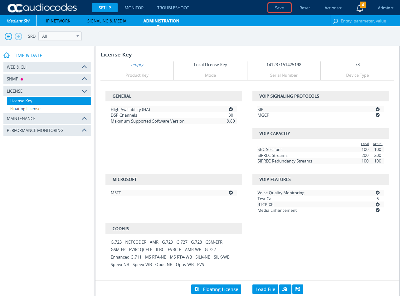
Verify the License
-
Connect to the AudioCodes SBC via web.
-
Click the ADMINISTRATION menu.
-
Under TIME & DATE, expand MAINTENANCE and select License Key.
-
Under VOIP FEATURES, verify that the license supports SBC Sessions and has enough capacity.
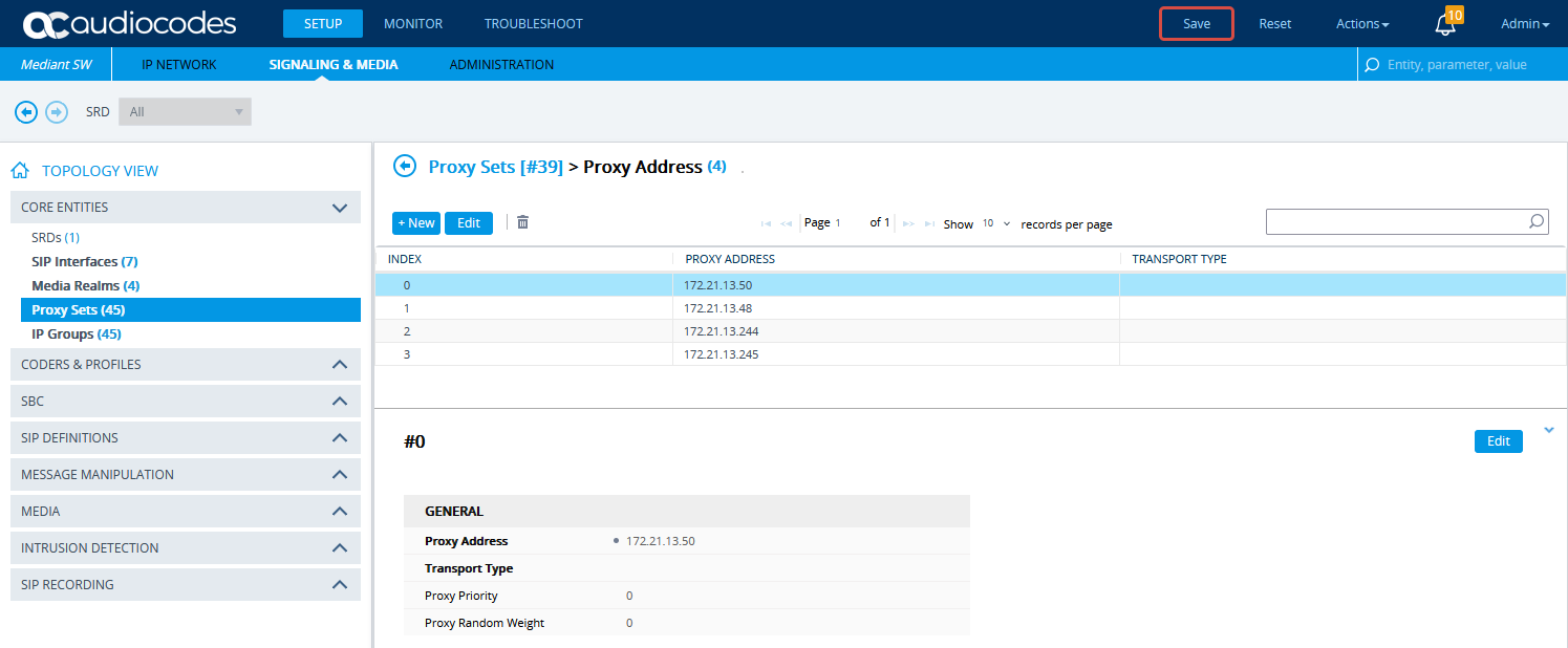
Configure the Proxy Set for NiCE CXone Environment
This procedure provides guidelines for configuring the SBC Proxy Set and the Proxy IP address for the NiCE CXone AudioCodes SBC for secure connection.
-
In the menu, click SIGNALING & MEDIA.
-
Under TOPOLOGY VIEW, expand CORE ENTITIES and select Proxy Sets.
-
In the list of Proxy Sets, click New.
-
In the Proxy Set window, under GENERAL:
-
In the Name field, enter a name.
-
From the SBC IPv4 SIP Interface drop-down list, select the SIP interface.
-
From the TLS Context Name drop-down list, select the TLS Context with the SBC certificate.
-
-
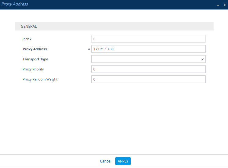
Scroll down and click the Proxy Address link.
-
In the Proxy Sets > Proxy Address window, click New and add the IP address for NiCE CXone AudioCodes SBC.
-
In the Proxy Address window, under GENERAL, in the Proxy Address field, enter the NiCE CXone AudioCodes SBC IP address and set the Transport Type to TLS.
-
Click APPLY.
Configure the Proxy Set for CUCM
This procedure provides guidelines for configuring the SBC for CUCM, including the IP addresses of the CUCM Publisher and Subscribers.
-
In the menu, click SIGNALING & MEDIA.
-
Under TOPOLOGY VIEW, expand CORE ENTITIES and select Proxy Sets.
-
In the list of Proxy Sets, click New.
-
In the Proxy Set window, under GENERAL:
-
In the Name field, enter a name.
-
From the SBC IPv4 SIP Interface drop-down list, select the SIP interface.
-
Click APPLY.
-
-
Scroll down and click the Proxy Address link.
-
In the Proxy Sets > Proxy Address window, click New and add the IP address for CUCM Publisher.
-
In the Proxy Address window, under GENERAL, in the Proxy Address field, enter the CUCM Publisher address.
-
Repeat steps 6 and 7 to add the IP address for CUCM Subscribers.
-
Click APPLY.
Configure Secure IP Profile
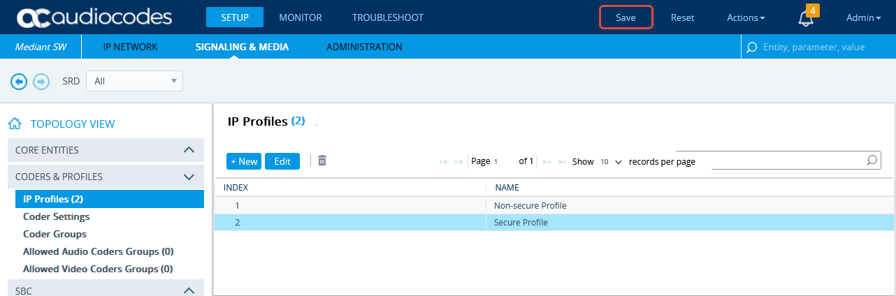
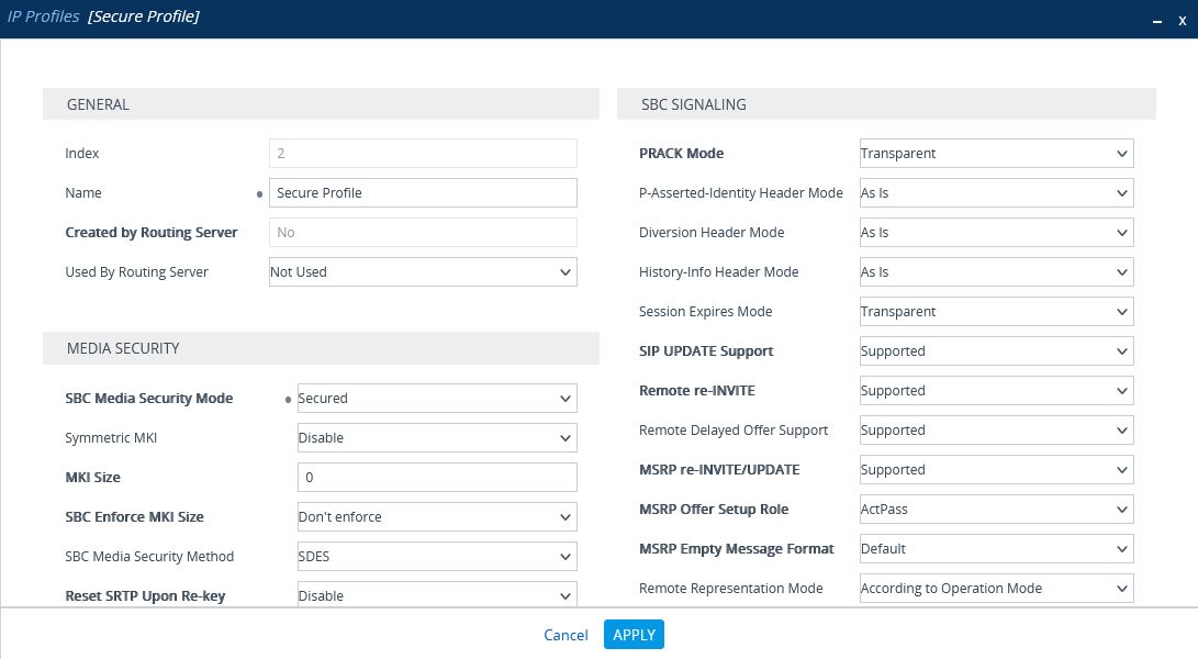
-
From the Setup menu, go to SIGNALING & MEDIA. Under TOPOLOGY VIEW, expand CODERS & PROFILES and select IP Profiles.
-
In the list of IP Profiles, click New.
-
In the list IP Profiles window, under MEDIA SECURITY, make sure the SBC Media Security Mode is set to Secured.
-
Click APPLY.
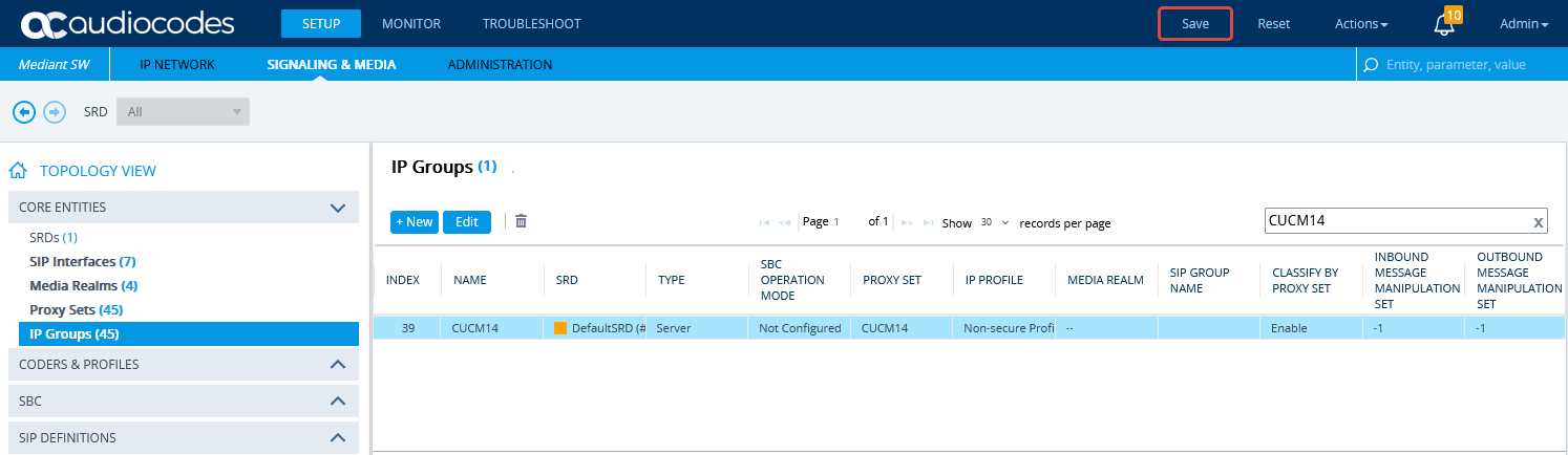
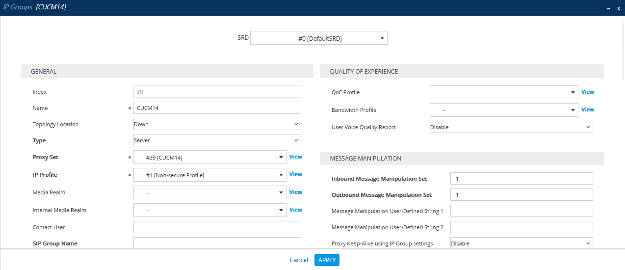
Configure the IP Group for CUCM
-
In the menu, click SIGNALING & MEDIA.
-
Under TOPOLOGY VIEW, expand CORE ENTITIES and select IP Groups.
-
In the list of IP Groups, click New.
-
In the IP Groups window, under GENERAL:
-
In the Index field, configure the next sequential number.
-
In the Name field, enter a name.
-
From the Topology Location drop-down list, select the location.
-
From the Type drop-down list, select Server.
-
From the Proxy Set field, select the CUCM Proxy Set for this IP Group.
-
In the IP Profile field, enter an existing non-secure IP Profile ID.
-
In the Media Realm Name field, select the existing Media Realm name.
-
-
Click APPLY.
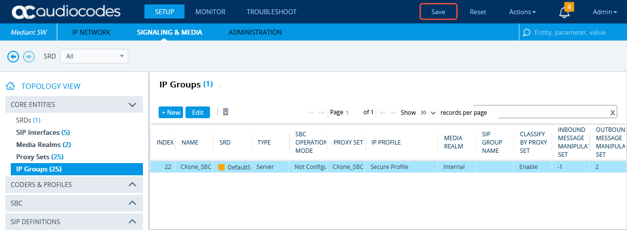
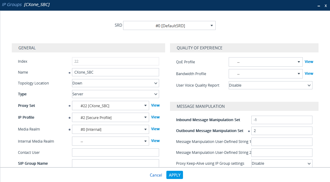
Configure the IP Group for NiCE CXone Environment
Verify that the secure IP Profile was configured. See Configure Secure IP Profile.
-
In the menu, click SIGNALING & MEDIA.
-
Under TOPOLOGY VIEW, expand CORE ENTITIES and select IP Groups.
-
In the list of IP Groups, click New.
-
In the IP Groups window, under GENERAL:
-
In the Index field, configure the next sequential number.
-
In the Name field, enter a name.
-
From the Topology Location drop-down list, select the location.
-
From the Type drop-down list, select Server.
-
From the Proxy Set field, select the NiCE CXone Proxy Set for this IP Group.
-
In the IP Profile field, select the secure IP Profile previously created in Configure Secure IP Profile.
-
In the Media Realm Name field, select the existing Media Realm name.
-
-
Click APPLY.
-
Then click Save.
Import and Export Certificates for TLS/SRTP
At the end of this step, you are required to provide to NiCE Professional Services:
-
The certificate in PEM format
Before import, the NiCE CXone AudioCodes SBC certificate must be saved in PEM format.
-
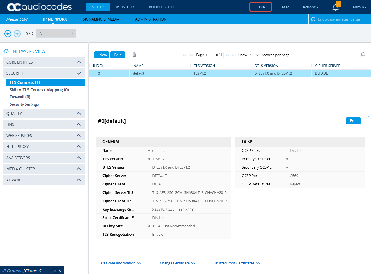
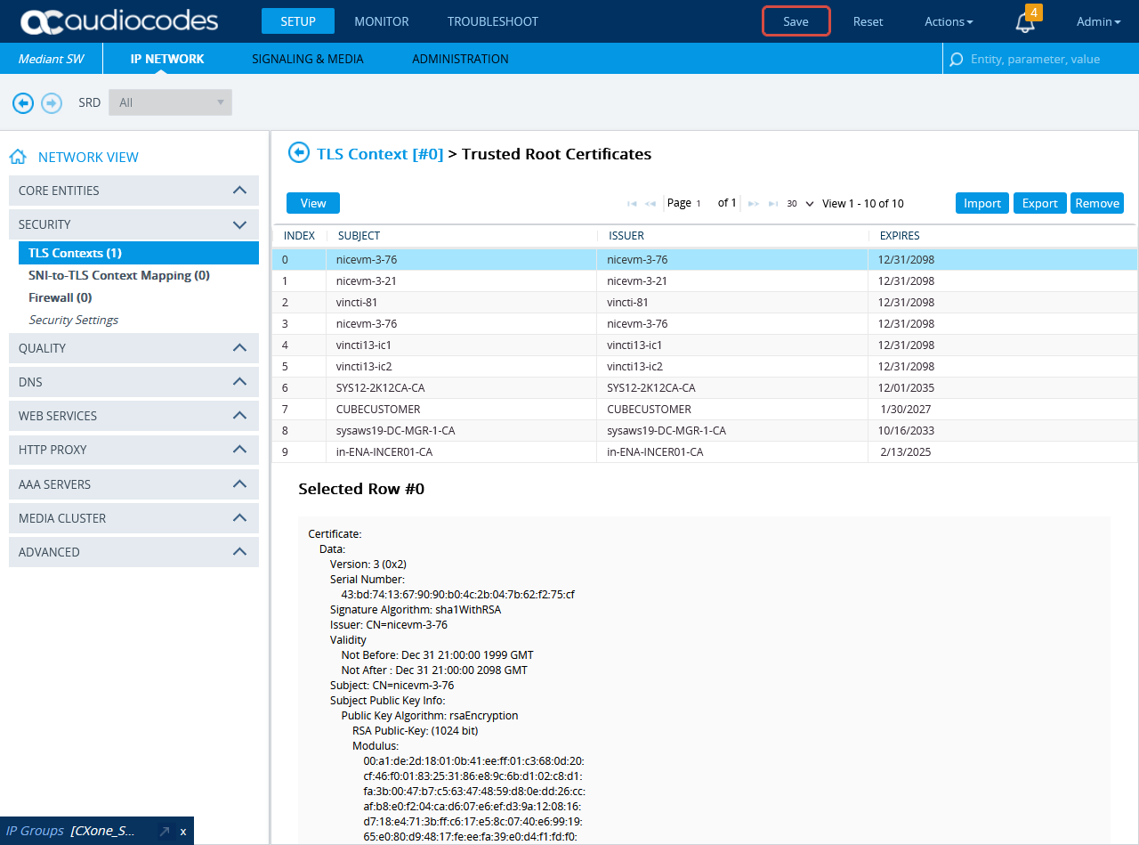
To import the NiCE CXone AudioCodes SBC certificate to the SBC, go to SETUP > IP NETWORK. Under NETWORK VIEW, expand SECURITY and select TLS Contexts.
-
In the TLS Context window, click Trusted Root Certificates.
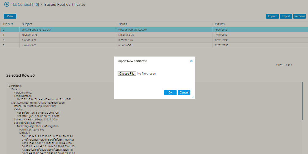
-
Click Import.
-
In the Import New Certificate window, click Choose File and browse to the NiCE CXone AudioCodes SBC certificate. Verify the NiCE CXone AudioCodes SBC certificate is in PEM format.
-
Click OK.
-
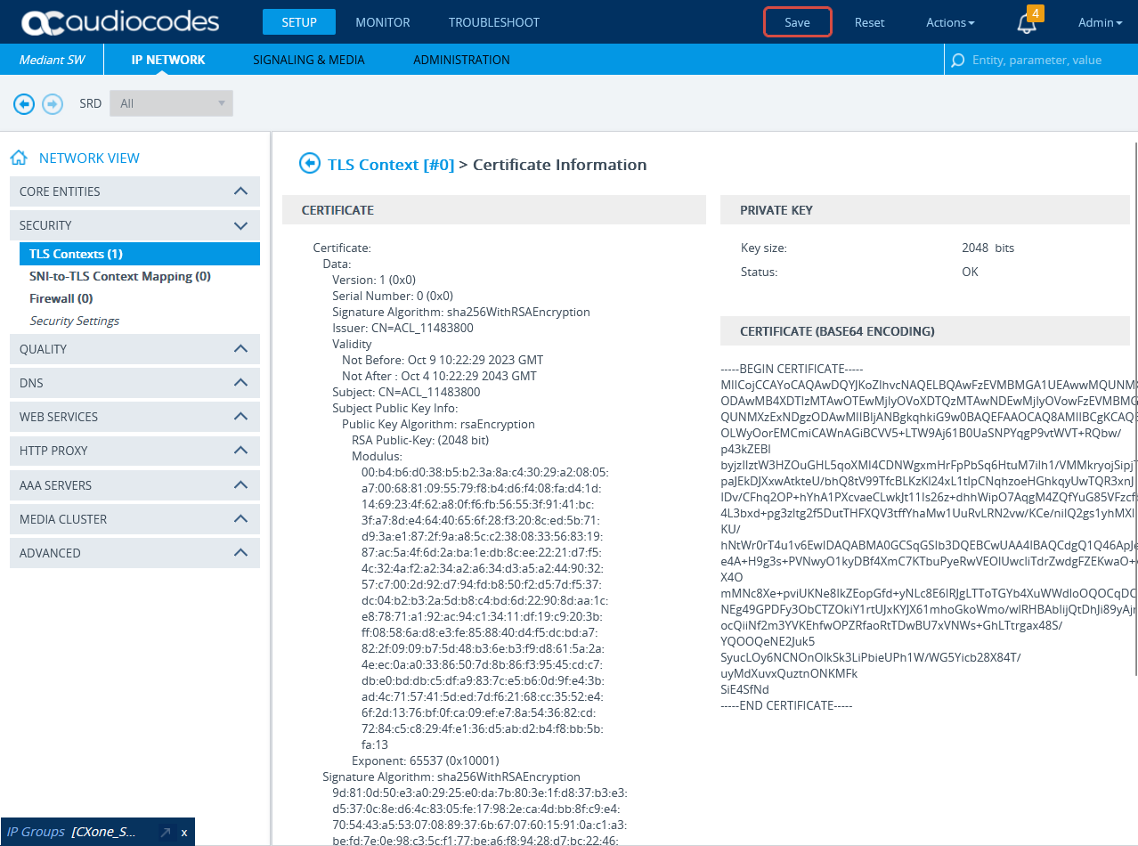
In the TLS Contexts window, click Certificate Information.
-
On the Certificate Information page, under CERTIFICATE, copy the text of the certificate. Create a certificate from this text.
-
Send the certificate in PEM format to the NiCE Professional Services together with the CA, if it exists.
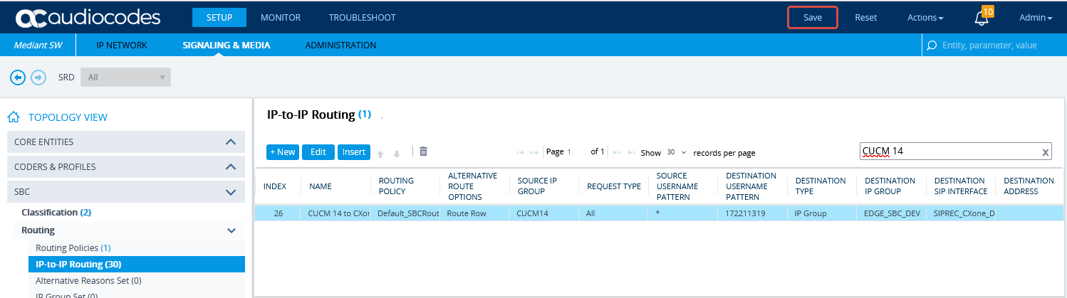
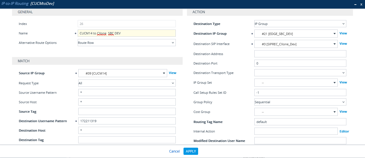
Configure IP-to-IP Routing
-
In the menu, click SIGNALING & MEDIA.
-
Under TOPOLOGY VIEW, expand SBC and select IP-to-IP Routing.
-
In the list of IP-to-IP Routing rules, click New.
-
In the IP-to-IP routing window:
-
In the Name field, enter a name, for example “From CUCM to NiCE CXone SBC”.
-
From the Source IP Group drop-down list, select the IP group created for CUCM in Configure the IP Group for CUCM.
-
In the Destination Username Pattern field, enter the pattern you plan to configure in Configure a New Route Pattern.
-
From the Destination IP Group drop-down list, select IP group created for NiCE CXone in Configure the IP Group for NiCE CXone Environment.
-
-
Click APPLY.
-
Then click Save.
Prepare Oracle (Acme Packet) SBC Environment
This section provides a workflow on how to configure all site components and prepare your Oracle (Acme Packet) Session Border Controller (SBC) for integration with both Real-Time Third Party Telephony Recording (Multi-ACD) and Cisco.
The SBC must have a valid TLS certificate installed. The certificate must be signed by a trusted Certificate Authority (CA) listed in the Supported Certificate Authorities for SIPREC section.
Phase 1: Site Preparation
IP Configuration
-
Ensure that the Oracle ACME SBC has one additional IP address per Internal and External Network interfaces.
-
The external IP address of the Oracle ACME SBC should be NAT'd with a public IP address on the firewall and must be able to communicate with the open Internet. NiCE Professional Services will provide the list of IPs and ports that should be allowed for SIP and RTP traffic.
Certificates
-
Export the Oracle ACME certificate/CA for NiCE Professional Services.
-
Get the NiCE CXone SBC CA certificate from NiCE Professional Services.
Phase 2: Configure Oracle SBC
To configure the Oracle SBC web interface, follow these recommended steps. The procedures should be executed by the Oracle site engineer exactly as described, without adding any extra settings for each entity. Leave any parameters not mentioned at their default values. An example configuration is provided in the Command Line Interface (CLI).
-
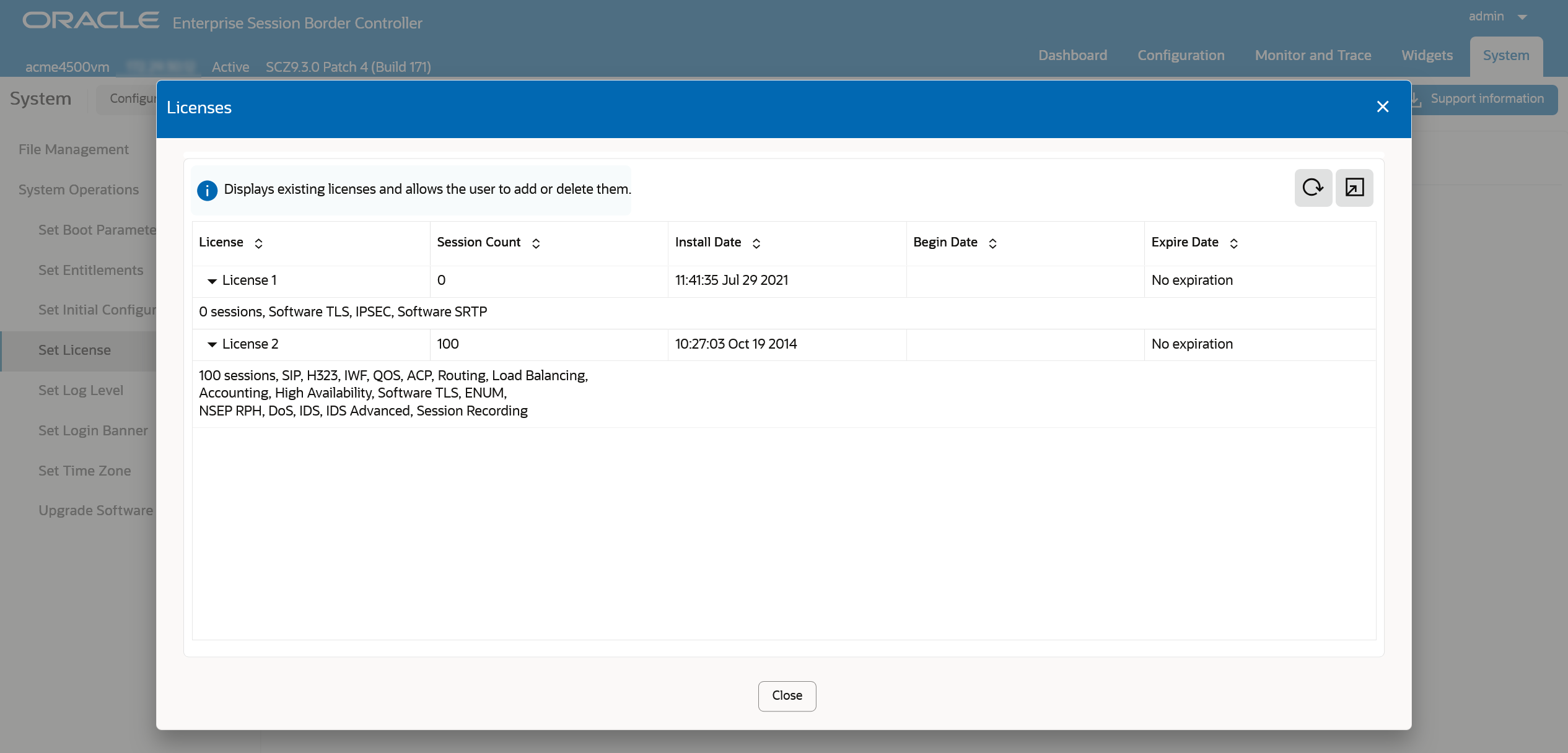
Go to System > System Operations > Set License and click View Current License Information.
-
Ensure the license includes Software TLS and Software SRTP.
-
Confirm the license is valid (not expired).
Upload NiCE CXone SBC Certificate
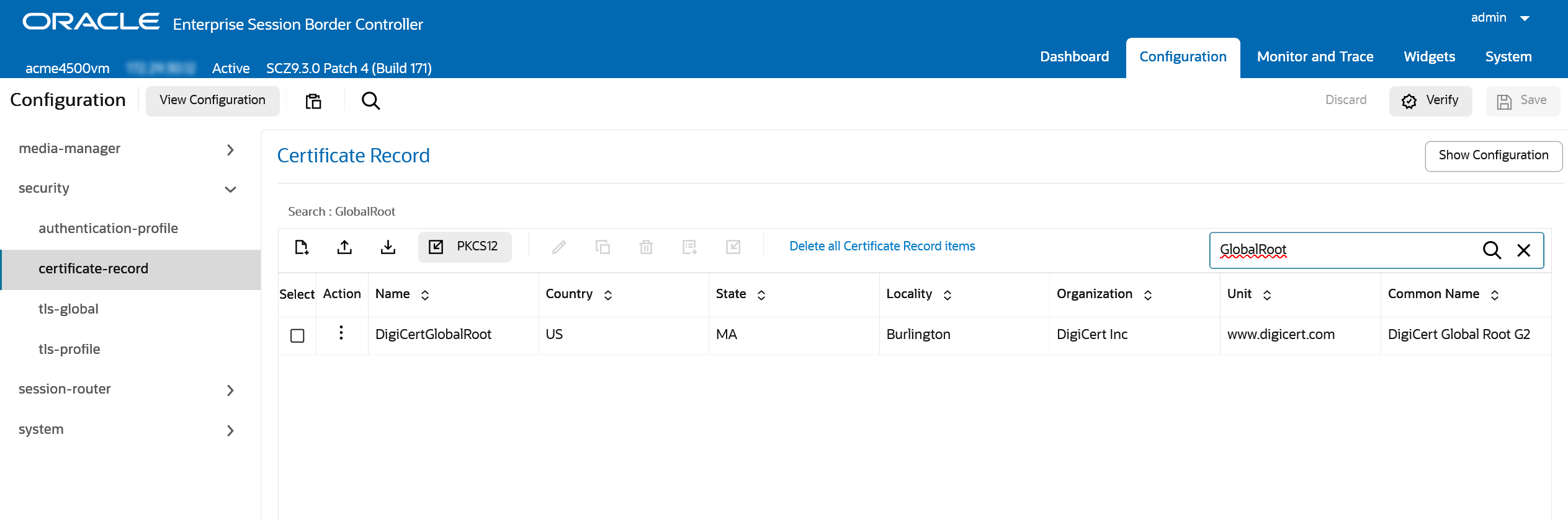
-
Go to Configuration > security > certificate-record.
-
Create a new record for the NiCE CXone SBC.
-
Return to the list of certificate records and import the certificate provided by NiCE Professional Services for the created entry.
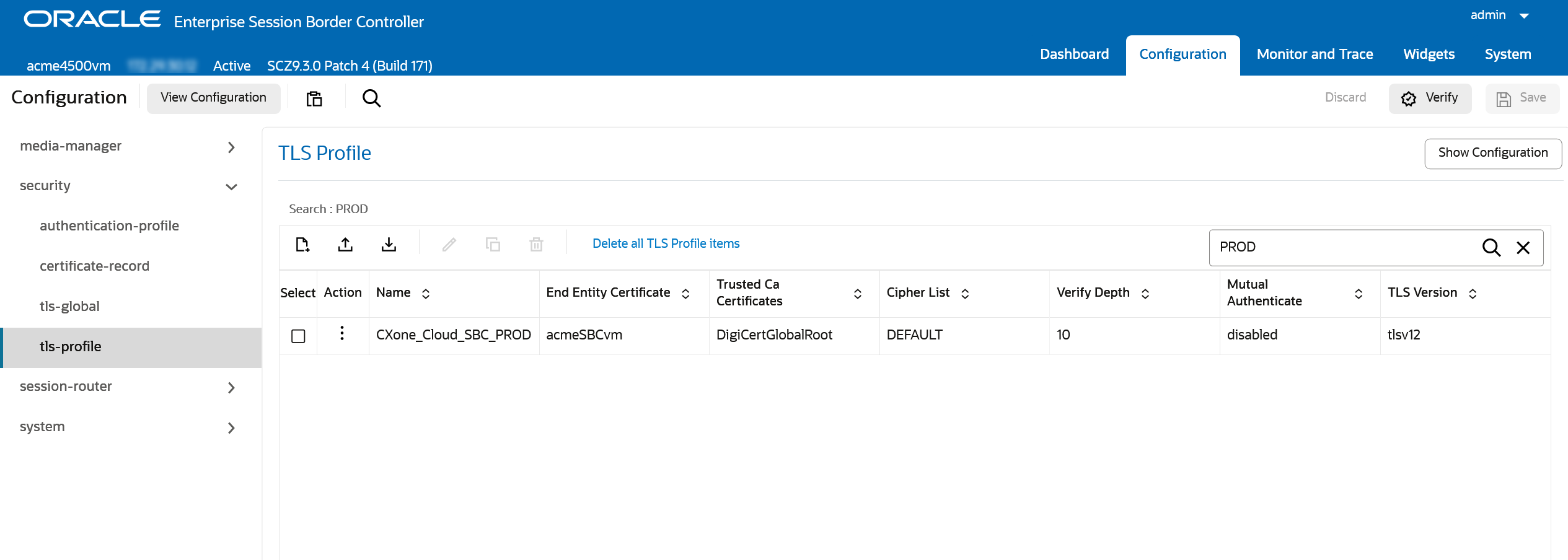
Configure TLS Profile for NiCE CXone SBC
-
Go to Configuration > security > tls-profile.
-
Create a new profile, for example, NiCE CXone SBC, with the following values:
-
End Entity Certificate is the Oracle ACME SBC certificate
-
Trusted CA Certificates is the certificate added in Upload NiCE CXone SBC Certificate.
-
Set TLS Version to 1.2
-
Set Cipher List to DEFAULT
-
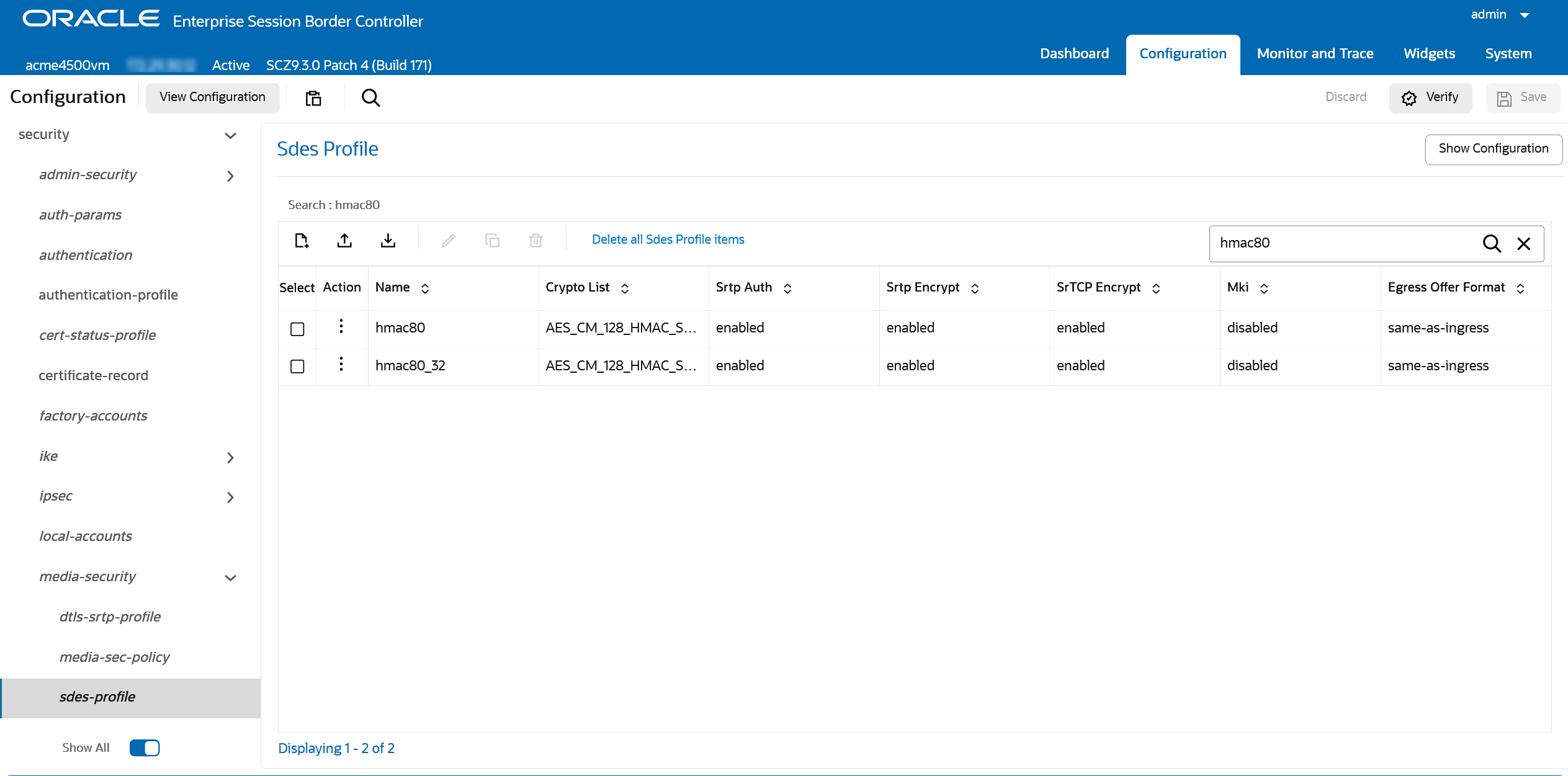
Configure SRTP and RTP Media Policies
-
Go to Configuration > security > media-security > sdes-profile.
Use Show All toggle at the bottom of the navigation pane to see all Advanced configuration objects.
-
Create a profile with either AES_CM_128_HMAC_SHA1_80 or AES_CM_128_HMAC_SHA1_32 ciphers.
CLI
var(--codeSnippetCopyLabel)sdes-profile
name hmac80
crypto-list AES_CM_128_HMAC_SHA1_80
srtp-auth enabled
srtp-encrypt enabled
srtcp-encrypt enabled
mki disabled
egress-offer-format same-as-ingress
use-ingress-session-params
options
key
salt
srtp-rekey-on-re-invite disabled
lifetime 0 -
Go to Configuration > security > media-security > media-sec-policy.
-
Create an SRTP media-sec-policy with the profile created in Configure TLS Profile for NiCE CXone SBC for both Inbound and Outbound sections. Set the Mode to SRTP.
CLI
var(--codeSnippetCopyLabel)media-sec-policy
name srtp_hmac80
pass-through disabled
options
inbound
profile hmac80_32
mode srtp
protocol sdes
hide-egress-media-update disabled
outbound
profile hmac80_32
mode srtp
protocol sdes -
Create an RTP media-sec-policy with an empty profile for both Inbound and Outbound sections. Set the Mode to RTP.
CLI
var(--codeSnippetCopyLabel)media-sec-policy
name rtp
pass-through disabled
options
inbound
profile
mode rtp
protocol none
hide-egress-media-update disabled
outbound
profile
mode rtp
protocol none
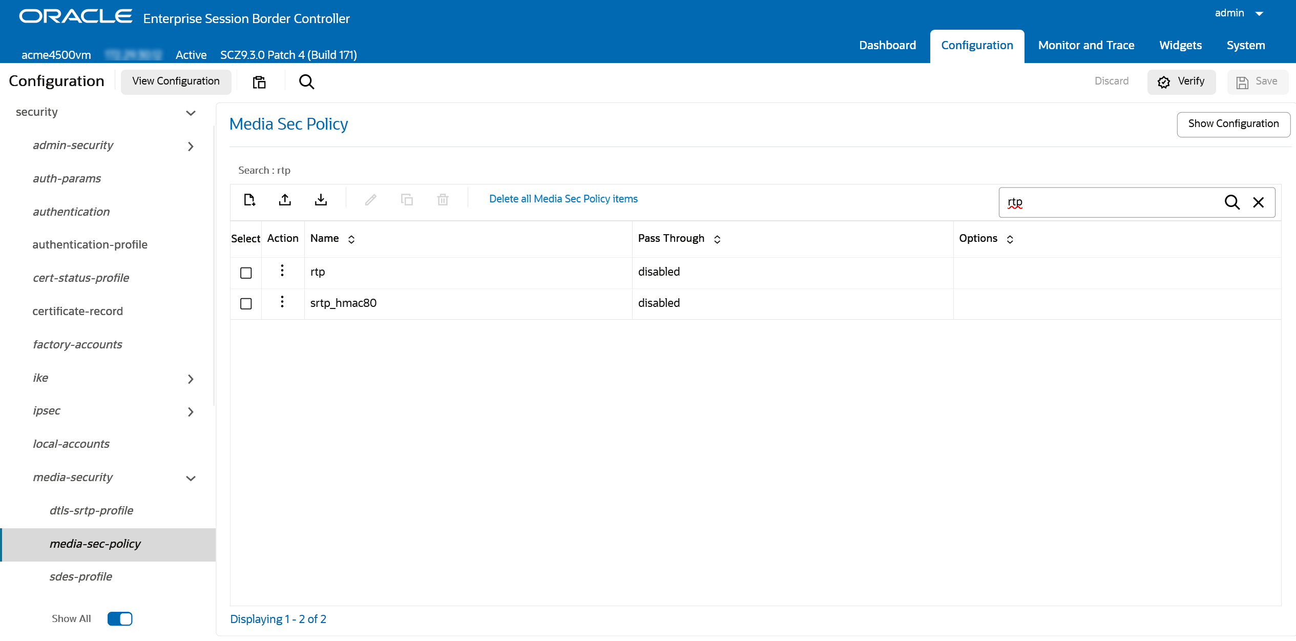
-
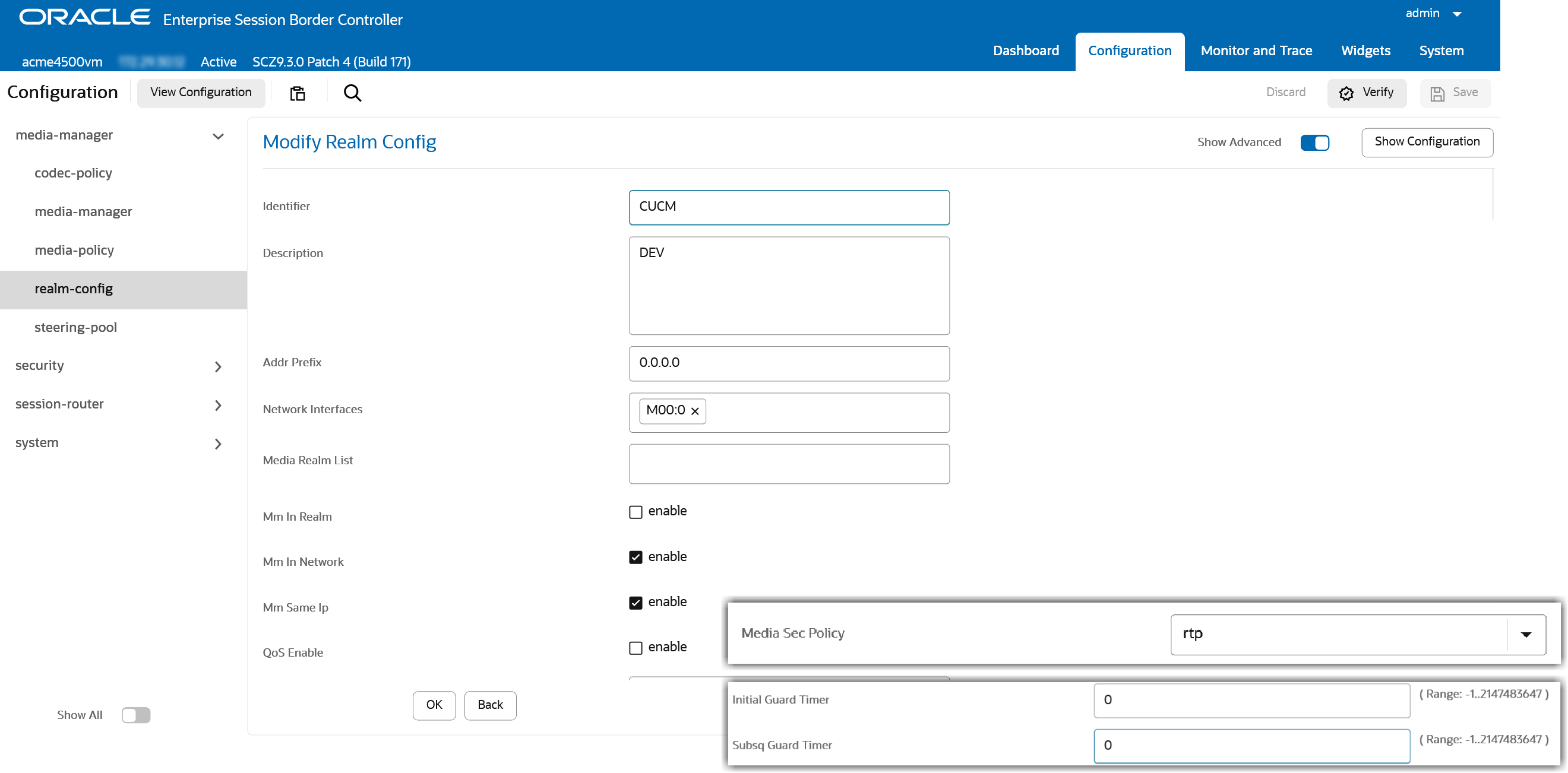
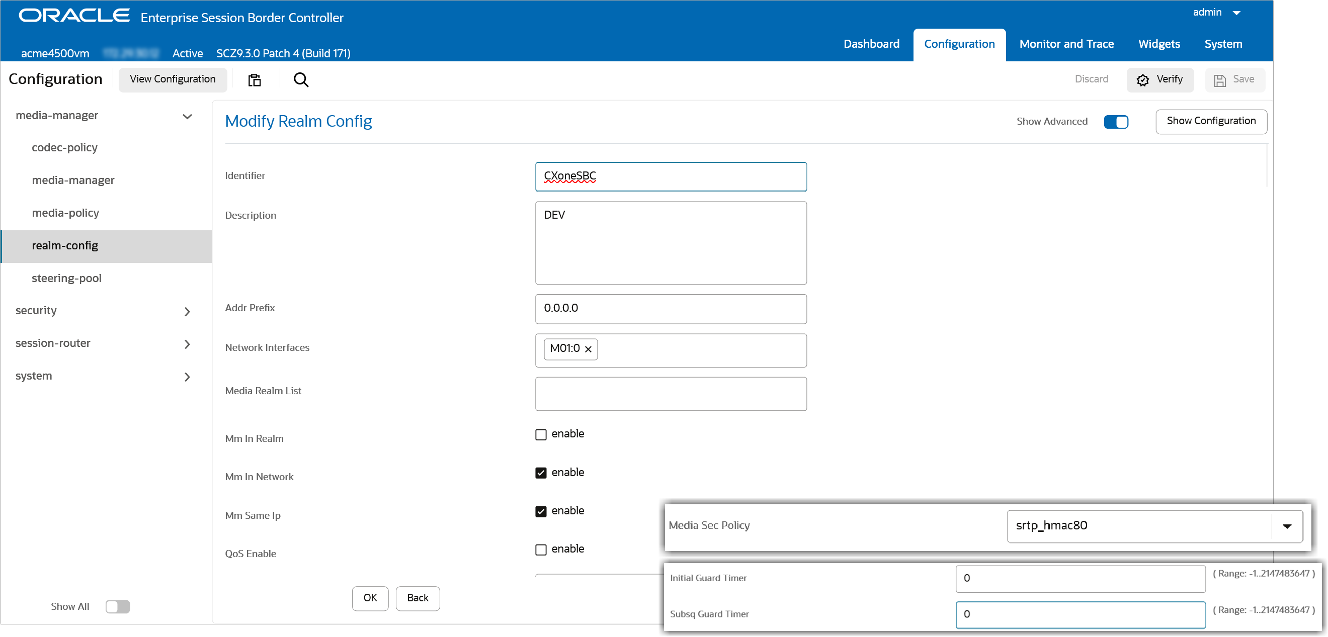
Go to Configuration > media-manager > realm-config.
-
Create a realm for CUCM with the following values:
-
Set Identifier to CUCM
-
Network Interface must be internal
-
Set Media Sec Policy to RTP
-
Set both Initial Guard Timer and Subsq Guard Timer to 0
CLI
var(--codeSnippetCopyLabel)realm-config
identifier CUCM
description DEV
addr-prefix 0.0.0.0
network-interfaces M00:0
media-realm-list
mm-in-realm disabled
mm-in-network enabled
mm-same-ip enabled
mm-in-system enabled
bw-cac-non-mm disabled
msm-release disabled
qos-enable disabled
max-bandwidth 0
fallback-bandwidth 0
max-priority-bandwidth 0
max-latency 0
max-jitter 0
max-packet-loss 0
observ-window-size 0
parent-realm
dns-realm
media-policy
nsep-media-policy
media-sec-policy rtp
rtcp-mux disabled
ice-profile
teams-fqdn
teams-fqdn-in-uri disabled
sdp-inactive-only disabled
dtls-srtp-profile
srtp-msm-passthrough disabled
class-profile
in-manipulationid
out-manipulationid
average-rate-limit 0
access-control-trust-level none
max-inbound-per-session-burst-rate 30
burst-rate-window-per-session 1
dos-action-at-session none
invalid-signal-threshold 0
maximum-signal-threshold 0
untrusted-signal-threshold 0
nat-trust-threshold 0
max-endpoints-per-nat 0
nat-invalid-message-threshold 0
wait-time-for-invalid-register 0
deny-period 30
session-max-life-limit 0
cac-failure-threshold 0
untrust-cac-failure-threshold 0
ext-policy-svr
diam-e2-address-realm
subscription-id-type END_USER_NONE
symmetric-latching disabled
pai-strip disabled
trunk-context
device-id
early-media-allow
enforcement-profile
additional-prefixes
restricted-latching none
restriction-mask 32
user-cac-mode none
user-cac-bandwidth 0
user-cac-sessions 0
icmp-detect-multiplier 0
icmp-advertisement-interval 0
icmp-target-ip
monthly-minutes 0
options
spl-options
accounting-enable enabled
net-management-control disabled
delay-media-update disabled
refer-call-transfer disabled
hold-refer-reinvite disabled
refer-notify-provisional none
dyn-refer-term disabled
codec-policy
codec-manip-in-realm disabled
codec-manip-in-network enabled
rtcp-policy
constraint-name
session-recording-server
session-recording-required disabled
manipulation-string
manipulation-pattern
stun-enable disabled
stun-server-ip 0.0.0.0
stun-server-port 3478
stun-changed-ip 0.0.0.0
stun-changed-port 3479
sip-profile
flow-time-limit -1
initial-guard-timer 0
subsq-guard-timer 0
tcp-flow-time-limit -1
tcp-initial-guard-timer -1
tcp-subsq-guard-timer -1
sip-isup-profile
match-media-profiles
qos-constraint
block-rtcp disabled
hide-egress-media-update disabled
tcp-media-profile
monitoring-filters
node-functionality
default-location-string
alt-family-realm
pref-addr-type none
sm-icsi-match-for-invite
sm-icsi-match-for-message
merge-early-dialogs disabled
user-site
srvcc-trfo
feature-trfo
fqdn-hostname
fqdn-hostname-in-header
P-Asserted-Identity
P-Asserted-Identity-For
nsep-stats disabled
steering-pool-threshold 0
steering-pool-lower-threshold 70
steering-pool-alarm-monitoring-time 15
suppress-hold-resume-reinvite disabled
snmp-sipmethod-stats disabled -
-
Create a realm for NiCE CXone SBC with the following values:
-
Set Identifier to CXoneSBC
-
Network Interface must be external
-
Set Media Sec Policy to SRTP
-
Enable the Delay Media Update and RTCP Mux features
-
Set both Initial Guard Timer and Subsq Guard Timer to 0
CLI
var(--codeSnippetCopyLabel)realm-config
identifier CXoneSBC
description DEV
addr-prefix 0.0.0.0
network-interfaces M01:0
media-realm-list
mm-in-realm disabled
mm-in-network enabled
mm-same-ip enabled
mm-in-system enabled
bw-cac-non-mm disabled
msm-release disabled
qos-enable disabled
max-bandwidth 0
fallback-bandwidth 0
max-priority-bandwidth 0
max-latency 0
max-jitter 0
max-packet-loss 0
observ-window-size 0
parent-realm
dns-realm
media-policy
nsep-media-policy
media-sec-policy srtp_hmac80
rtcp-mux enabled
ice-profile
teams-fqdn
teams-fqdn-in-uri disabled
sdp-inactive-only disabled
dtls-srtp-profile
srtp-msm-passthrough disabled
class-profile
in-manipulationid
out-manipulationid
average-rate-limit 0
access-control-trust-level none
max-inbound-per-session-burst-rate 30
burst-rate-window-per-session 1
dos-action-at-session none
invalid-signal-threshold 0
maximum-signal-threshold 0
untrusted-signal-threshold 0
nat-trust-threshold 0
max-endpoints-per-nat 0
nat-invalid-message-threshold 0
wait-time-for-invalid-register 0
deny-period 30
session-max-life-limit 0
cac-failure-threshold 0
untrust-cac-failure-threshold 0
ext-policy-svr
diam-e2-address-realm
subscription-id-type END_USER_NONE
symmetric-latching disabled
pai-strip disabled
trunk-context
device-id
early-media-allow
enforcement-profile
additional-prefixes
restricted-latching none
restriction-mask 32
user-cac-mode none
user-cac-bandwidth 0
user-cac-sessions 0
icmp-detect-multiplier 0
icmp-advertisement-interval 0
icmp-target-ip
monthly-minutes 0
options
spl-options
accounting-enable enabled
net-management-control disabled
delay-media-update enabled
refer-call-transfer disabled
hold-refer-reinvite disabled
refer-notify-provisional none
dyn-refer-term disabled
codec-policy
codec-manip-in-realm disabled
codec-manip-in-network enabled
rtcp-policy
constraint-name
session-recording-server
session-recording-required disabled
manipulation-string
manipulation-pattern
stun-enable disabled
stun-server-ip 0.0.0.0
stun-server-port 3478
stun-changed-ip 0.0.0.0
stun-changed-port 3479
sip-profile
flow-time-limit -1
initial-guard-timer 0
subsq-guard-timer 0
tcp-flow-time-limit -1
tcp-initial-guard-timer -1
tcp-subsq-guard-timer -1
sip-isup-profile
match-media-profiles
qos-constraint
block-rtcp disabled
hide-egress-media-update disabled
tcp-media-profile
monitoring-filters
node-functionality
default-location-string
alt-family-realm
pref-addr-type none
sm-icsi-match-for-invite
sm-icsi-match-for-message
merge-early-dialogs disabled
user-site
srvcc-trfo
feature-trfo
fqdn-hostname
fqdn-hostname-in-header
P-Asserted-Identity
P-Asserted-Identity-For
nsep-stats disabled
steering-pool-threshold 0
steering-pool-lower-threshold 70
steering-pool-alarm-monitoring-time 15
suppress-hold-resume-reinvite disabled
snmp-sipmethod-stats disabled -
-
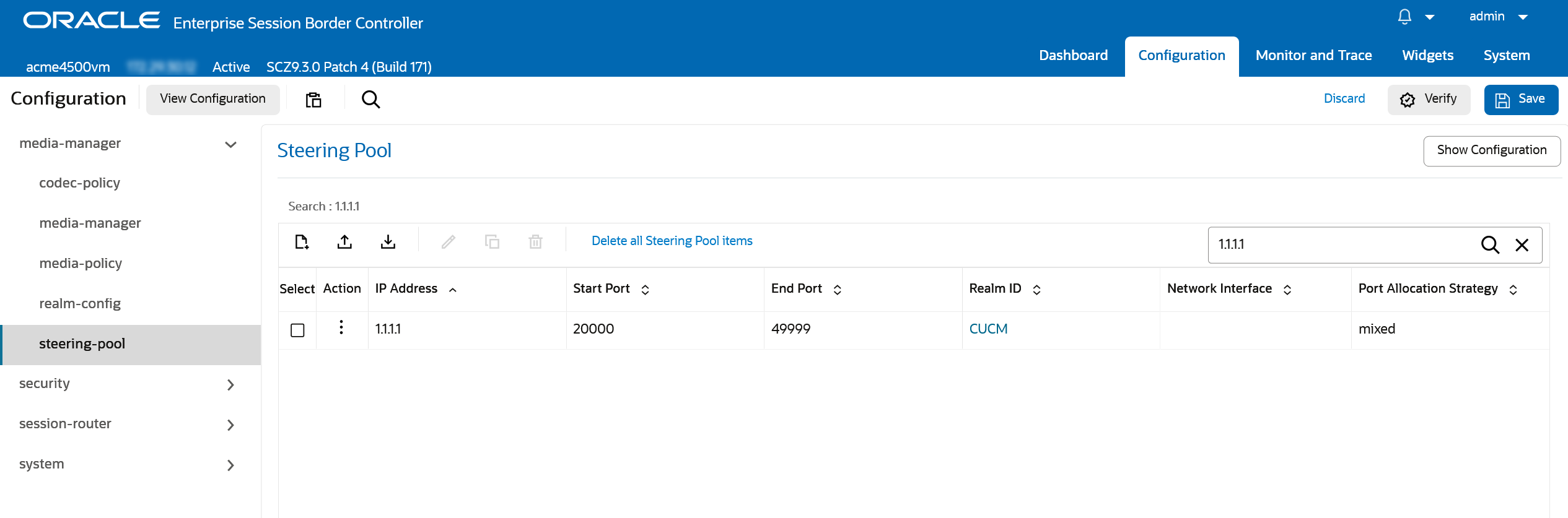
Go to Configuration > media-manager > steering-pool.
-
Create a pool for the external leg (NiCE CXone SBC) with the corresponding IPs and realm configured in Configure Realms. Start Port and End Port can be any value within the allowed range from 0 to 65535.
CLI
var(--codeSnippetCopyLabel)steering-pool
ip-address 2.2.2.2
start-port 20000
end-port 49999
realm-id CXoneSBC
network-interface
port-allocation-strategy mixed -
Create a pool for the internal leg (CUCM) with the corresponding IPs and realm configured in Configure Realms. Start Port and End Port can be any value within the allowed range from 0 to 65535.
CLI
var(--codeSnippetCopyLabel)steering-pool
ip-address 1.1.1.1
start-port 20000
end-port 49999
realm-id CUCM
network-interface
port-allocation-strategy mixed
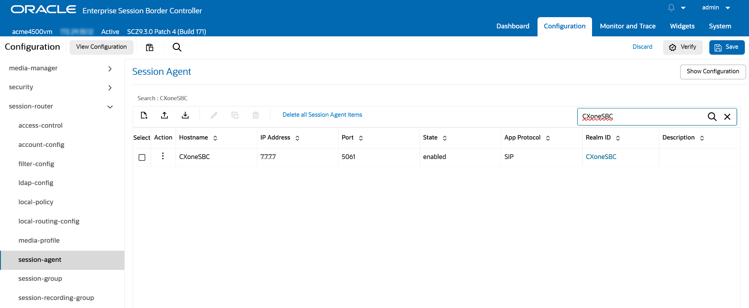
Configure Session Agent for NiCE CXone SBC
-
Go to Configuration > session-router > session-agent.
-
Create a session agent for NiCE CXone SBC with the following values:
-
Set Hostname to CXoneSBC
-
Enter the NiCE CXone SBC IP Address provided by NiCE Professional Services
-
Set Port to 5061 for a secured TLS connection or 5065 for a mutual TLS (mTLS) connection.
-
For Transport Method, choose StaticTLS
-
Use the Realm ID created for NiCE CXone SBC in Configure Realms
CLI
var(--codeSnippetCopyLabel)session-agent
hostname CXoneSBC
ip-address 44.240.214.243
port 5061
state enabled
app-protocol SIP
app-type
transport-method StaticTLS
realm-id CXoneSBC
egress-realm-id
description
carriers
allow-next-hop-lp enabled
associated-agents
constraints disabled
max-sessions 0
max-inbound-sessions 0
max-outbound-sessions 0
max-burst-rate 0
max-inbound-burst-rate 0
max-outbound-burst-rate 0
max-sustain-rate 0
max-inbound-sustain-rate 0
max-outbound-sustain-rate 0
min-seizures 5
min-asr 0
cac-trap-threshold 0
session-max-life-limit 0
time-to-resume 0
ttr-no-response 0
in-service-period 0
burst-rate-window 0
sustain-rate-window 0
max-inbound-per-session-burst-rate 30
burst-rate-window-per-session 1
dos-action-at-session inherit
req-uri-carrier-mode None
proxy-mode
redirect-action
loose-routing enabled
send-media-session enabled
response-map
ping-method
ping-interval 0
ping-send-mode keep-alive
ping-all-addresses disabled
ping-in-service-response-codes
out-service-response-codes
load-balance-dns-query hunt
options
spl-options
media-profiles
trust-me disabled
request-uri-headers
stop-recurse
local-response-map
ping-to-user-part
ping-from-user-part
ping-response disabled
in-manipulationid
out-manipulationid
manipulation-string
manipulation-pattern
p-asserted-id
trunk-group
max-register-sustain-rate 0
early-media-allow
invalidate-registrations disabled
rfc2833-mode none
rfc2833-payload 0
codec-policy
enforcement-profile
emergency-dscp-profile
refer-call-transfer disabled
refer-notify-provisional none
reuse-connections NONE
tcp-keepalive none
tcp-reconn-interval 0
max-register-burst-rate 0
register-burst-window 0
sip-profile
sip-isup-profile
kpml-interworking inherit
kpml2833-iwf-on-hairpin inherit
precedence 0
monitoring-filters
session-recording-server
session-recording-required disabled
hold-refer-reinvite disabled
send-tcp-fin disabled
sip-recursion-policy
sm-icsi-match-for-invite
sm-icsi-match-for-message
fax-servers
trigger-oos-alarm disabled
static-tcp-source-port 0 -
-
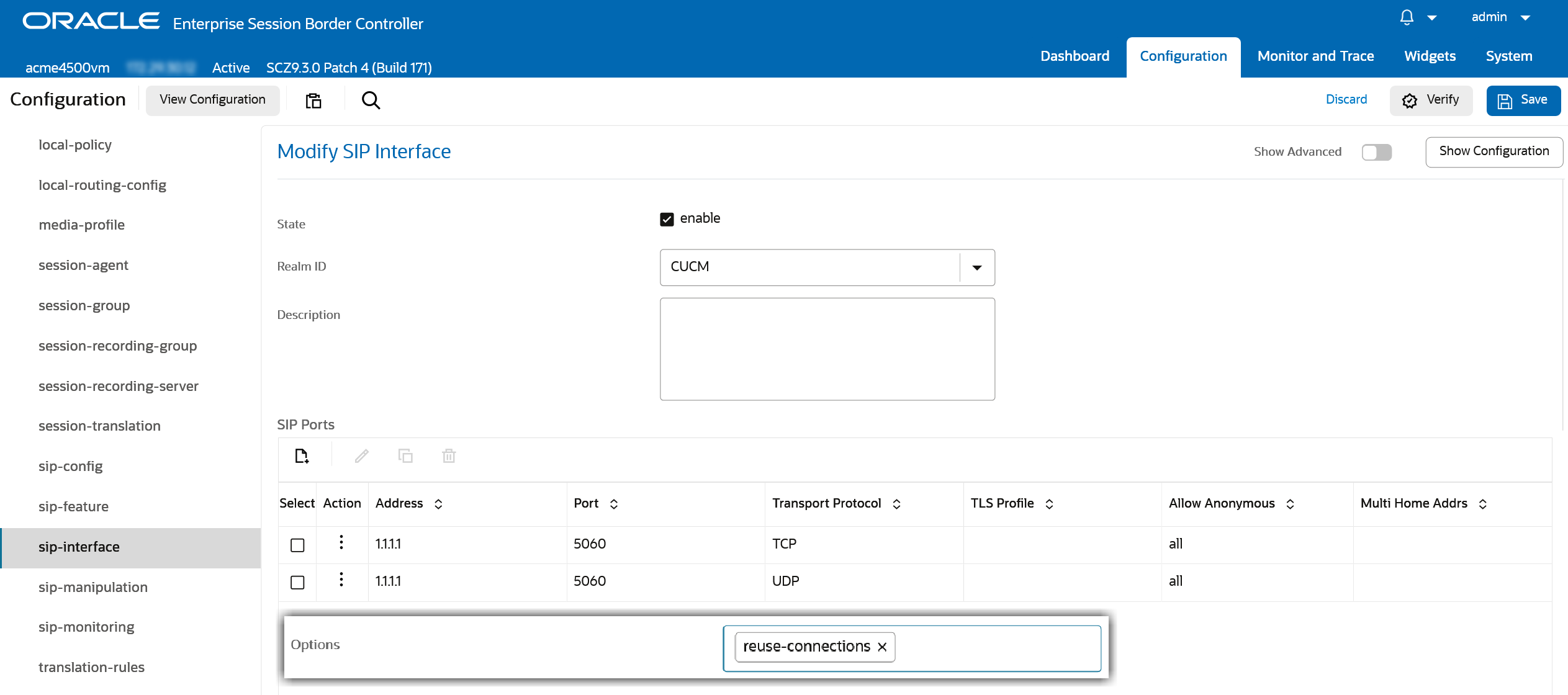
Go to Configuration > Session-router > sip-interface.
-
Create a SIP Interface for CUCM with the following values:
-
Enable State
-
From the Realm ID drop-down, select CUCM
-
Set the IP Address
-
Set Port to 5060
-
For Transport Protocol, choose UDP and/or TCP
-
Set Options to reuse-connections
CLI
var(--codeSnippetCopyLabel)sip-interface
state enabled
realm-id CUCM
description
sip-port
address 1.1.1.1
port 5060
transport-protocol TCP
tls-profile
allow-anonymous all
multi-home-addrs
ims-aka-profile
sip-port
address 1.1.1.1
port 5060
transport-protocol UDP
tls-profile
allow-anonymous all
multi-home-addrs
ims-aka-profile
carriers
trans-expire 0
initial-inv-trans-expire 0
invite-expire 0
session-max-life-limit 0
max-redirect-contacts 0
proxy-mode
redirect-action
contact-mode none
nat-traversal none
nat-interval 30
tcp-nat-interval 90
registration-caching disabled
min-reg-expire 300
registration-interval 3600
route-to-registrar disabled
secured-network disabled
teluri-scheme disabled
uri-fqdn-domain
options reuse-connections
spl-options
trust-mode all
max-nat-interval 3600
nat-int-increment 10
nat-test-increment 30
sip-dynamic-hnt disabled
tcp-max-nat-interval 3600
tcp-nat-int-increment 10
tcp-nat-test-increment 30
tcp-sip-dynamic-hnt disabled
stop-recurse 401,407
port-map-start 0
port-map-end 0
in-manipulationid
out-manipulationid
sip-ims-feature disabled
sip-atcf-feature disabled
subscribe-reg-event disabled
operator-identifier
anonymous-priority none
max-incoming-conns 0
per-src-ip-max-incoming-conns 0
inactive-conn-timeout 0
untrusted-conn-timeout 0
network-id
ext-policy-server
ldap-policy-server
default-location-string
term-tgrp-mode none
charging-vector-mode pass
charging-function-address-mode pass
ccf-address
ecf-address
implicit-service-route disabled
rfc2833-payload 101
rfc2833-mode transparent
constraint-name
response-map
local-response-map
sec-agree-feature disabled
sec-agree-pref ipsec3gpp
enforcement-profile
emergency-dscp-profile
route-unauthorized-calls
tcp-keepalive none
add-sdp-invite disabled
add-sdp-in-msg
p-early-media-header disabled
p-early-media-direction
add-sdp-profiles
add-sdp-profiles-in-msg
manipulation-string
manipulation-pattern
sip-profile
sip-isup-profile
tcp-conn-dereg 0
tunnel-name
register-keep-alive none
kpml-interworking disabled
kpml2833-iwf-on-hairpin disabled
msrp-delay-egress-bye disabled
send-380-response
pcscf-restoration
session-timer-profile
session-recording-server
session-recording-required disabled
service-tag
reg-cache-route disabled
diversion-info-mapping-mode none
atcf-icsi-match
sip-recursion-policy
asymmetric-preconditions disabled
asymmetric-preconditions-mode send-with-nodelay
sm-icsi-match-for-invite
sm-icsi-match-for-message
s8hr-profile
fax-continue-session none
npli-profile
hist-to-div-for-cause-380 inherit
user-agent
allow-diff2833-clock-rate-mode disabled -
-
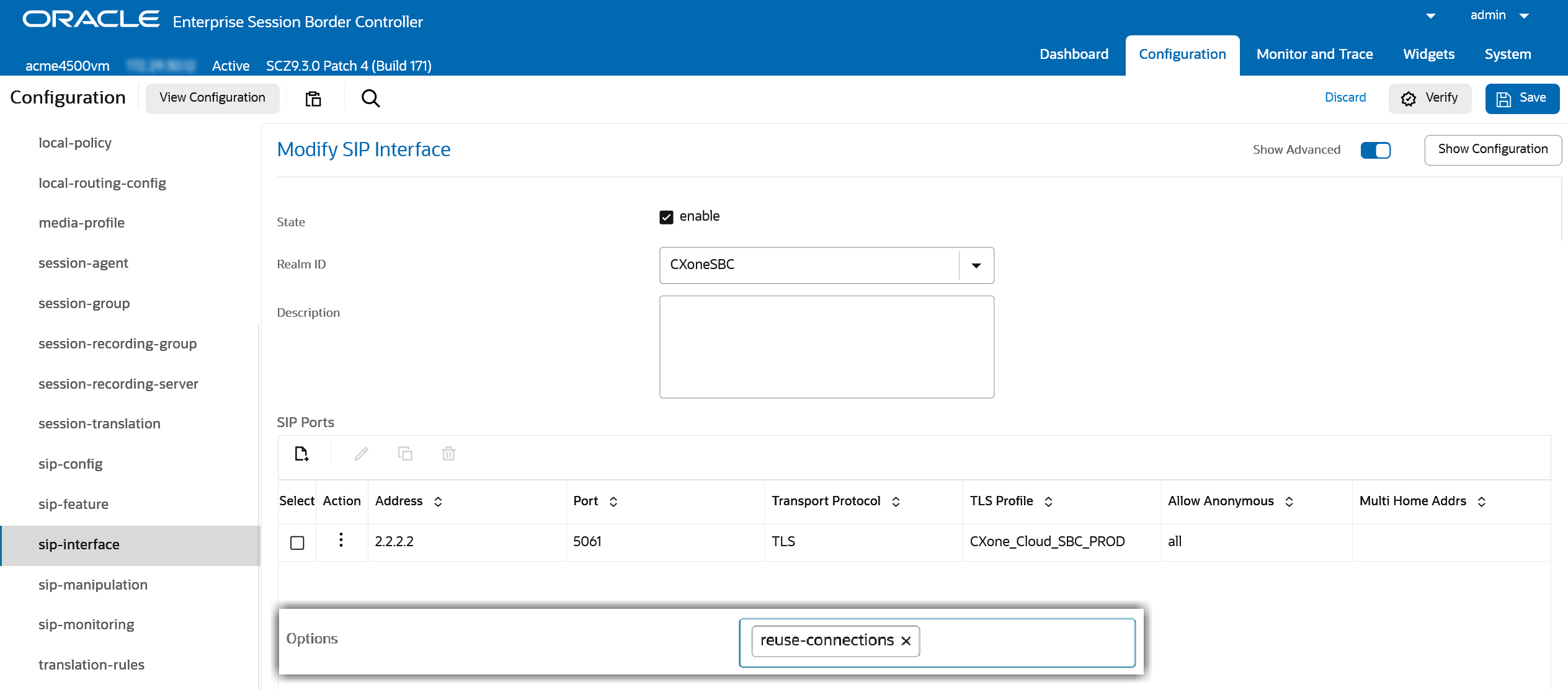
Create a SIP Interface for NiCE CXone SBC with the following values:
-
Enable State
-
From the Realm ID drop-down, select CXoneSBC
-
Set the IP Address
-
Set Port to 5061 for a secured TLS connection or 5065 for a mutual TLS (mTLS) connection.
-
For Transport Protocol, choose TLS
-
Select TLS Profile created in Configure TLS Profile for NiCE CXone SBC.
-
Set Options to reuse-connections
CLI
var(--codeSnippetCopyLabel)sip-interface
state enabled
realm-id CXoneSBC
description
sip-port
address 2.2.2.2
port 5061
transport-protocol TLS
tls-profile CXoneSBC
allow-anonymous all
multi-home-addrs
ims-aka-profile
carriers
trans-expire 0
initial-inv-trans-expire 0
invite-expire 0
session-max-life-limit 0
max-redirect-contacts 0
proxy-mode
redirect-action
contact-mode none
nat-traversal none
nat-interval 30
tcp-nat-interval 90
registration-caching disabled
min-reg-expire 300
registration-interval 3600
route-to-registrar disabled
secured-network disabled
teluri-scheme disabled
uri-fqdn-domain
options reuse-connections
spl-options HeaderNatPublicSipIfIp=3.3.3.3,HeaderNatPrivateSipIfIp=2.2.2.2
trust-mode all
max-nat-interval 3600
nat-int-increment 10
nat-test-increment 30
sip-dynamic-hnt disabled
tcp-max-nat-interval 3600
tcp-nat-int-increment 10
tcp-nat-test-increment 30
tcp-sip-dynamic-hnt disabled
stop-recurse 401,407
port-map-start 0
port-map-end 0
in-manipulationid
out-manipulationid
sip-ims-feature disabled
sip-atcf-feature disabled
subscribe-reg-event disabled
operator-identifier
anonymous-priority none
max-incoming-conns 0
per-src-ip-max-incoming-conns 0
inactive-conn-timeout 0
untrusted-conn-timeout 0
network-id
ext-policy-server
ldap-policy-server
default-location-string
term-tgrp-mode none
charging-vector-mode pass
charging-function-address-mode pass
ccf-address
ecf-address
implicit-service-route disabled
rfc2833-payload 101
rfc2833-mode transparent
constraint-name
response-map
local-response-map
sec-agree-feature disabled
sec-agree-pref ipsec3gpp
enforcement-profile
emergency-dscp-profile
route-unauthorized-calls
tcp-keepalive none
add-sdp-invite disabled
add-sdp-in-msg
p-early-media-header disabled
p-early-media-direction
add-sdp-profiles
add-sdp-profiles-in-msg
manipulation-string
manipulation-pattern
sip-profile
sip-isup-profile
tcp-conn-dereg 0
tunnel-name
register-keep-alive none
kpml-interworking disabled
kpml2833-iwf-on-hairpin disabled
msrp-delay-egress-bye disabled
send-380-response
pcscf-restoration
session-timer-profile
session-recording-server
session-recording-required disabled
service-tag
reg-cache-route disabled
diversion-info-mapping-mode none
atcf-icsi-match
sip-recursion-policy
asymmetric-preconditions disabled
asymmetric-preconditions-mode send-with-nodelay
sm-icsi-match-for-invite
sm-icsi-match-for-message
s8hr-profile
fax-continue-session none
npli-profile
hist-to-div-for-cause-380 inherit
user-agent
allow-diff2833-clock-rate-mode disabled -
-
Additionally, configure the proper NAT settings within the SIP messages for the NiCE CXone SBC SIP interface using the SPL options. For more details, refer to the SBC Behind a NAT Device Option section in Oracle SBC Configuration Guide.
-
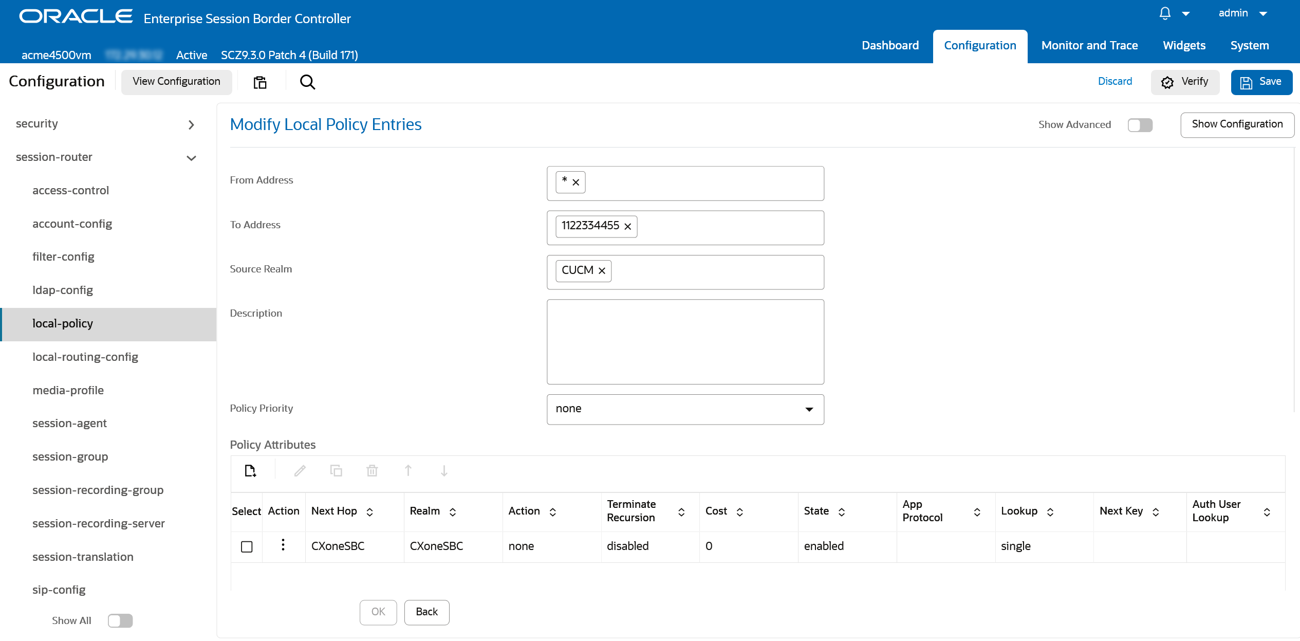
Go to Configuration > session-router > local-policy.
-
Create a new policy with the following values:
-
From Address can be any value, for example *
-
To Address is set to the Route Pattern configured on CUCM for the Recording Profile
-
Source Realm is set to the CUCM realm
-
-
Add a Policy Attribute:
-
Set Next Hop to the Session agent configured in Configure Session Agent for NiCE CXone SBC
-
Set Realm to CXoneSBC.
CLI
var(--codeSnippetCopyLabel)local-policy
from-address *
to-address 44240214243
source-realm CUCM
description
activate-time
deactivate-time
state enabled
parallel-forking disabled
policy-priority none
policy-attribute
next-hop CXoneSBC
realm CXoneSBC
action none
terminate-recursion disabled
carrier
start-time 0000
end-time 2400
days-of-week U-S
cost 0
state enabled
app-protocol
methods
media-profiles
lookup single
next-key
auth-user-lookup
eloc-str-lkup disabled
eloc-str-match -
-
Check the configuration is correct and click Save to apply the changes.
Prepare Ribbon (Sonus) SBC Environment
This section outlines the steps required to configure the Ribbon (Sonus) Session Border Controller (SBC) for integration with Real-Time Third Party Telephony Recording (Multi-ACD) and Cisco Unified Communications Manager (CUCM).
The configuration should be performed by a certified Ribbon engineer.
All steps must be followed precisely, and any parameters not explicitly mentioned should remain at their default values.
Phase 1: Site Preparation
This phase ensures the SBC is properly prepared for integration by configuring IP interfaces, certificates, and network accessibility.
IP Configuration
-
Ensure the Ribbon (Sonus) SBC has one additional IP interface for both the Internal and External Networks.
-
For each additional IP interface, create separate SIP Signaling Ports under the corresponding Zone.
-
Assign a TLS profile to the External SIP Signaling Port. This profile must include the certificate used for communication with the CXone SBC.
-
NAT the external IP address of the SBC to a public IP address on the firewall.
-
Ensure the SBC can access the open Internet.
-
Obtain the list of required IP addresses and ports for SIP and SRTP traffic from NiCE Professional Services and allow them through the firewall.
Certificate Management
The SBC must have a valid TLS certificate installed. The certificate must be signed by a trusted Certificate Authority (CA) listed in the Supported Certificate Authorities for SIPREC section.
-
Export the Ribbon SBC certificate and certificate authority (CA) bundle for delivery to NiCE Professional Services.
-
Get the NiCE CXone SBC CA certificate from NiCE Professional Services.
-
Import the CXone CA certificate into the SBC.
Phase 2: Configure Ribbon (Sonus) SBC
This phase details the configuration of profiles, trunk groups, and routing to enable communication between CUCM and CXone SBC.
Create Transparency Profile
To ensure SIP headers (e.g., From) are passed to CXone for call correlation, create a Transparency profile that will be attached later to the CUCM and CXone SBC trunk groups:
-
Log into SBC EMA interface.
-
Navigate to Configuration > Profile Management > Service Profiles > Transparency Profiles.
-
Create a new profile named Pass_From_Header with State set to Disabled.
-
Under the SIP Header section, add the from SIP header.
-
Save the header entry.
-
Enable the Pass_From_Header Transparency Profile.


Create IP Signaling Profiles for Encrypted and Non-Encrypted Communication
Depending on your deployment requirements, create dedicated IP Signaling Profiles for both encrypted (TLS) and non-encrypted (UDP/TCP) communication. These profiles will be used later when configuring trunk groups for CUCM and CXone SBC.
-
Navigate to EMA Interface > Configuration > Profile Management > Signaling Profiles > IP Signaling Profile.
-
Create two separate profiles:
-
One for TLS (secure) communication
-
One for non-TLS (non-secure) communication
-
-
For each profile, set the IP Protocol Type to SIP Only.
-
In the Egress IP Attributes section:
-
For the TLS profile, set Type1 Transport to TLS Over TCP
-
For the non-TLS profile, set Type1 Transport to UDP or TCP, depending on your network requirements
-
-
Save each profile after configuration.


Create Packet Service Profile for SRTP and RTP
Depending on your deployment requirements, create dedicated Packet Service Profiles for both secure (SRTP) and non-secure (RTP) media transport. These profiles will be used later when configuring trunk groups for CUCM and CXone SBC.
-
Navigate to EMA Interface > Configuration > Profile Management > Media Profiles > Packet Service Profile.
-
Create two separate profiles:
-
One for SRTP (secure) media
-
One for RTP (non-secure) media
-
-
For the SRTP profile:
-
Go to the Secure Rtp RTCP section and in the Crypto Suite Profile dropdown, select the appropriate encryption suite (e.g., AES128_HMAC_32_80).
-
Go to the Flags section and enable the Enable SRTP option.
-
-
Save the profile.


Configure Trunk Groups for CUCM and CXone SBC
To enable SIP communication between the SBC, CUCM, and CXone, create dedicated trunk groups for each system. These trunk groups will use the signaling, media, and transparency profiles configured earlier.
For CXone SBC:
-
Navigate to EMA Interface > Configuration > System Provisioning > SIP Trunk Group.
-
Create a new trunk group with the following settings:
-
State: Enabled.
-
Mode: In Service.
-
Under Media, from the Packet Service Profile dropdown, select SRTP.
-
Under Signaling, from the IP Signaling Profile dropdown, select TLS.
-
Under Service, from the Transparency Profile dropdown, select the Transparency Profile created earlier.
-
Under Media, the Media IP Interface Group Name must match the External IP Interface Group
-


For CUCM:
-
Navigate to EMA Interface > Configuration > System Provisioning > SIP Trunk Group.
-
Create a new trunk group with the following settings:
-
State: Enabled
-
Mode: In Service
-
Under Media, from the Packet Service Profile dropdown, select RTP
-
Under Signaling, select the non-secure IP Signaling Profile from the dropdown
-
Under Service, from the Transparency Profile dropdown, select the Transparency Profile created earlier
-
Under Media, the Media IP Interface Group Name must match the Internal IP Interface Group
-
-
After creating the CUCM trunk group, proceed to the Ingress IP Prefix section and add all IP addresses of the CUCM cluster.

Create IP Peer for CXone SBC
To enable routing to the CXone SBC, you must create a dedicated IP Peer under the External Zone. This peer will be referenced in the routing configuration.
-
Navigate to EMA Interface > Configuration > System Provisioning > IP Peer.
-
Create a new IP Peer with the following settings:
-
Zone: External
-
Under IP Peer List, enter the Name (e.g., CXone_DEV)
-
Use the IP Address provided by NiCE Professional Services
-
Under Signaling, from the IP Signaling Profile dropdown, select TLS
-
Port: 5060
-
-
Save the configuration.

Configure Routing
To route calls from CUCM to the CXone SBC, create a Routing Label and define a Route using the previously configured trunk group and IP peer.
-
Navigate to EMA Interface > Configuration > System Provisioning > Routing.
-
Create a new Routing Label with ID (Name) CXone_SBC.
-
Under this label, create a Routing Label Route Sequence with the following settings:
-
Route Type: Trunk Group
-
Zone: External (for the CXone Trunk Group)
-
Trunk Group: Select the CXone SBC Trunk Group
-
IP Peer: Select the CXone SBC IP Peer
-
-
Save the Routing Label configuration.
-
Go to the Routes tab and create a new route with the following settings:
-
Route Type: Trunk Group
-
Ingress Trunk Group: Select the CUCM Trunk Group
-
Routing Label: Select CXone_SBC created earlier
-
-
Save the configuration to apply the changes.


Configure Network Based Recording (NBR) with Additional SBC
This section includes information on Network Based Recording (NBR) method, which can source the media from either the phone or the gateway.
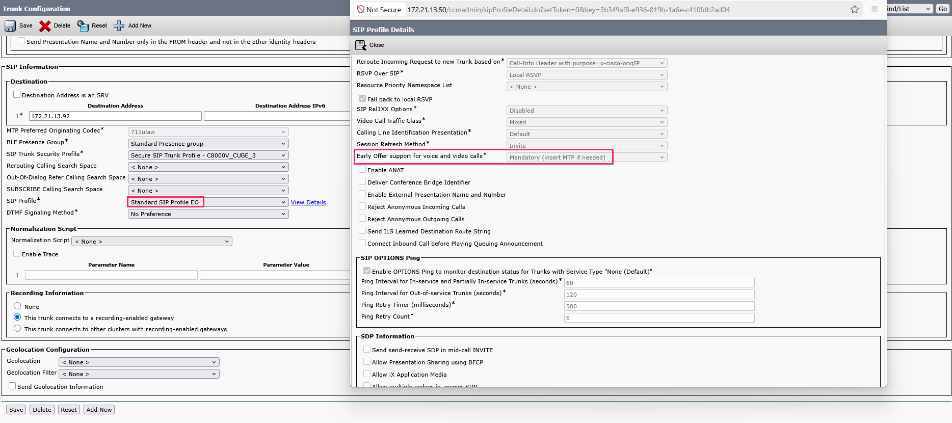
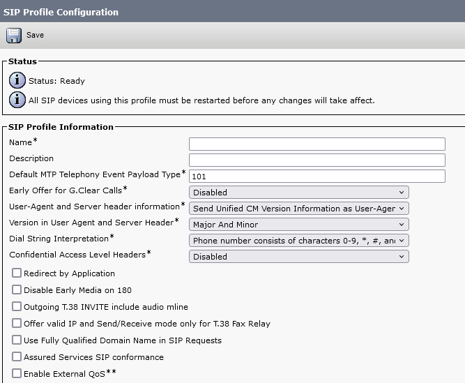
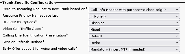
Configure a SIP Profile
A SIP![]() Protocol used for signaling and controlling multimedia communication sessions such as voice and video calls. Profile is required to configure the SIP Trunk to support the Early Offer mode.
Protocol used for signaling and controlling multimedia communication sessions such as voice and video calls. Profile is required to configure the SIP Trunk to support the Early Offer mode.
Use this procedure to configure a SIP profile with common SIP settings that you can assign to SIP devices and trunks that use this profile.
-
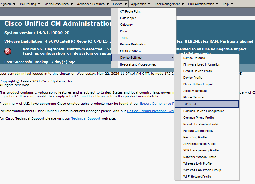
Go to Device > Device Settings > SIP Profile.
-
In the Find and List SIP Profiles window, click Add New.
-
In the SIP Profile Configuration window, under SIP Profile Information, in the Name field, enter a name.
-
Under Trunk Specific Configuration:
-
From the Early Offer support for voice and video calls drop-down list, select Mandatory (insert MTP if needed).
-
-
Click Save.
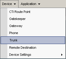
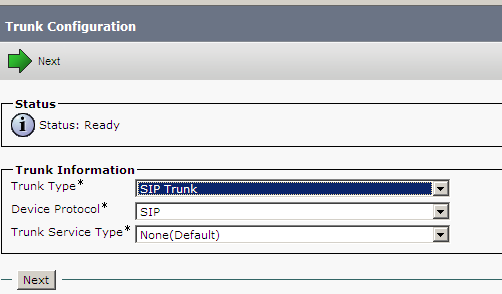
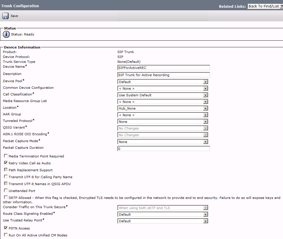
Configure a SIP Trunk
A SIP![]() Protocol used for signaling and controlling multimedia communication sessions such as voice and video calls. Trunk is required to connect the CUCM to the additional SBC configured in Configure Additional SBC as SIP and Media Proxy.
Protocol used for signaling and controlling multimedia communication sessions such as voice and video calls. Trunk is required to connect the CUCM to the additional SBC configured in Configure Additional SBC as SIP and Media Proxy.
-
Go to Device > Trunk.
-
In the Find and List Trunks window, click Add New.
-
In the Trunk Configuration window, in the Trunk Information area, from the Trunk Type list, select SIP Trunk. The Device Protocol is automatically set as SIP and the Trunk Service Type appears.
-
Click Next.
-
In the Device Information area:
-
In the Device Name field enter a name.
-
In the Description field, enter a description.
-
From the Device Pool list, select the device pool for your network.
-
-
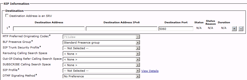
In the SIP Information area.
-
In the Destination Address field, enter the additional SBC IP address configured in Configure Additional SBC as SIP and Media Proxy.
-
Verify that the Destination Port is set to the listening port of your additional SBC. By default, it is 5060.
-
From the SIP Trunk Security Profile list, select a standard non-secure profile. (The name of the profile will vary from site to site, in the example here the profile name is Non-Secure SIP Trunk Profile.)
You can create several security profiles according to your site administration requirements and network topology.
-
From the SIP Profile list, select the name of the SIP Profile you created in Configure a SIP Profile.
-
Click Save.
-
-
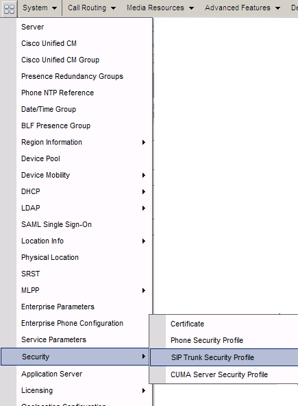
Verify the SIP Trunk Security Profile configuration:
-
Go to System > Security > SIP Trunk Security Profile.
The Find and List SIP Trunk Security Profiles window appears.
-
Click Find.
-
From the list of SIP Trunk Security Profiles, select the SIP Trunk Security Profile.
-
In the SIP Trunk Security Profile Configuration area, for standard Cisco JTAPI active configurations, verify Outgoing Transport Type is set to TCP.
-
-
Click Save.
-
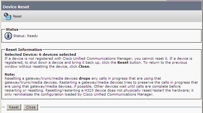
Click Reset.
-
Click Reset.

Configure a Recording Profile
In Real-Time Third Party Telephony Recording (Multi-ACD), each device that needs recording is associated with a Recording Profile that defines the number that it uses to route to the additional SBC.
-
Verify that a SIP Trunk was configured.
-
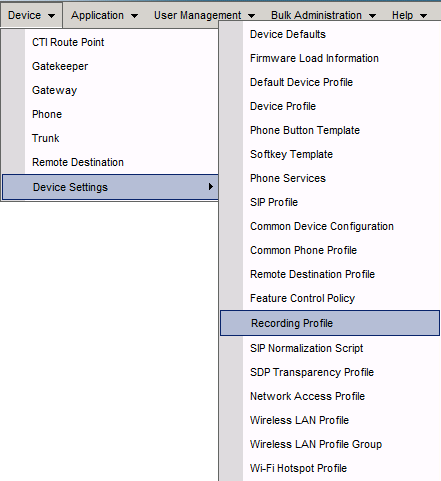
Go to Device > Device Settings > Recording Profile.
-
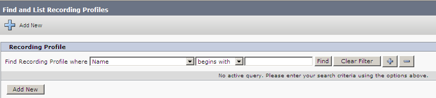
In the Find and List Recording Profiles window, click Add New.
-
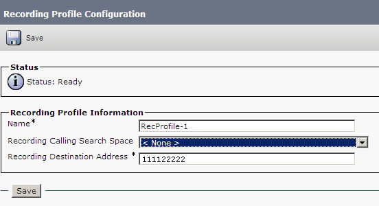
In the Recording Profile Configuration window, in the Recording Profile Information area, configure:
Field/List
Description
value
Recording Calling Search Space
Use this to dial the SIP Trunk
Recording CSS Recording Destination Address
The number that refers to the local SBC SIP Trunk
The number that refers to the additional SBC SIP Trunk.
-
Click Save.
Configure a Route Group
You now need to configure a new Route Group to group the SIP Trunk.
-
Verify that the Recording Profile was configured.
-
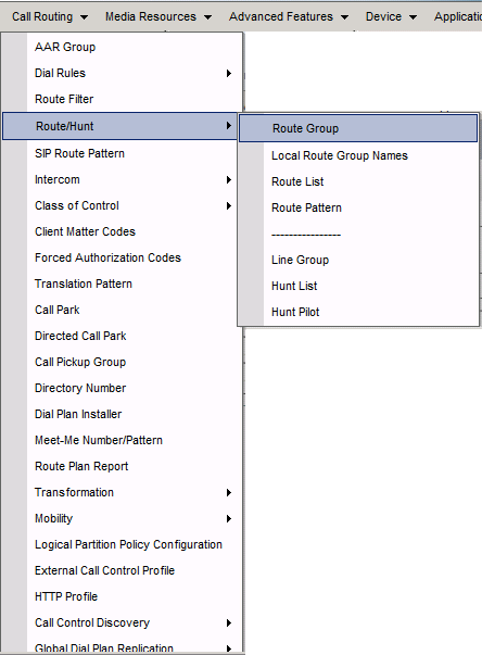
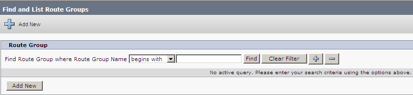
Go to Call Routing > Route/Hunt > Route Group.
-
In the Find and List Route Groups window, click Add New.
-
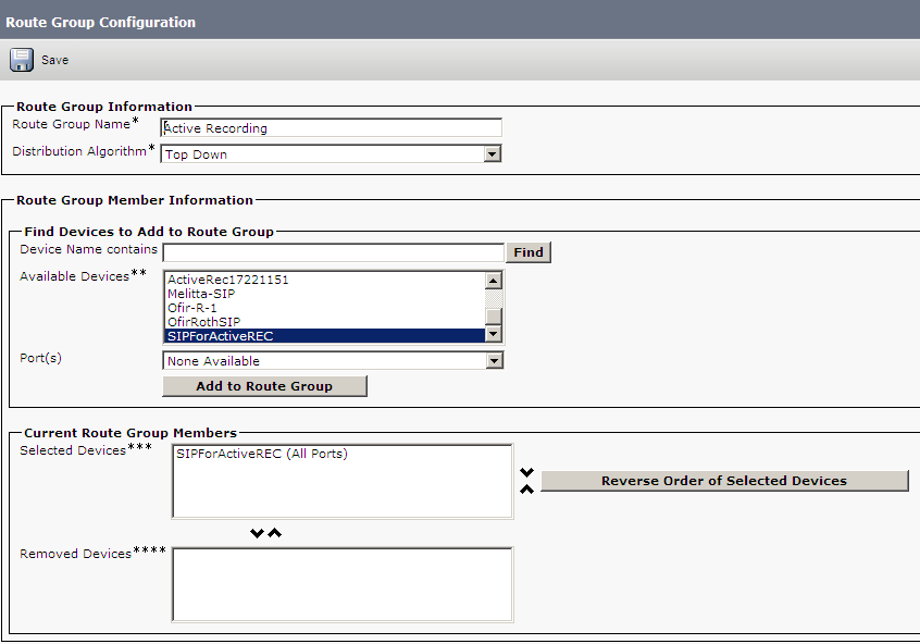
In the Route Group Configuration window, in the Route Group Information area, in the Route Group Name field, enter a name.
-
From the Distribution Algorithm list, select Top Down.
-
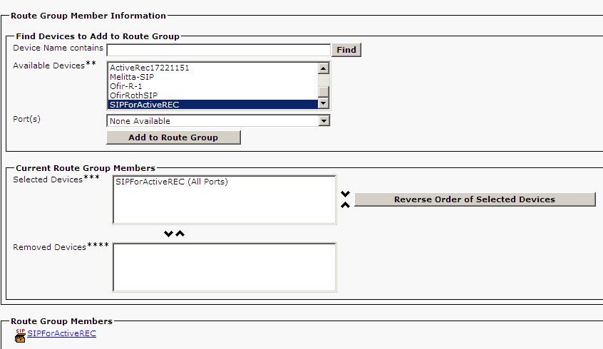
In the Find Devices to Add to Route Group area, in the Available Devices list, scroll to select the SIP Trunk created in Configure a SIP Trunk.
-
Click Add to Route Group. In the Current Route Group Members area, the SIP trunk appears in the Selected Devices list.
-
To add another device to the Current Route Group Members area, repeat steps 6 and 7.
-
Click Save.
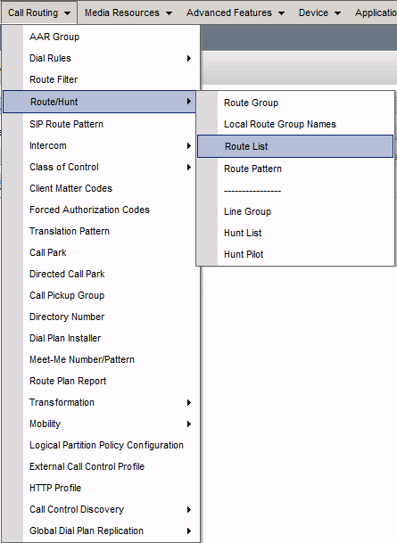
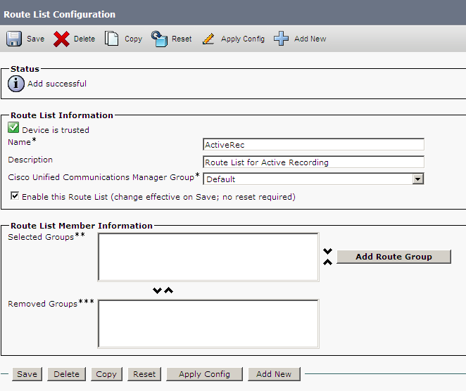
Configure a New Route List
Define a new Route List that contains the Recorder Route Group.
-
Verify that the Recording Profile was configured.
-
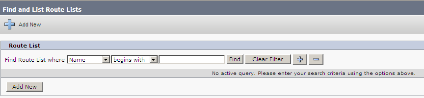
Go to Call Routing > Route/Hunt > Route List.
-
In the Find and List Route Groups window, click Add New.
-
In the Route List Information area, in the Route List Name field, enter a name.
-
From the Cisco Unified Communications Manager Group list, select the CUCM group for your site.
-
Click Save.
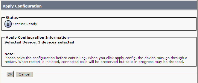
-
Click Apply Config.
-
Click OK.
-
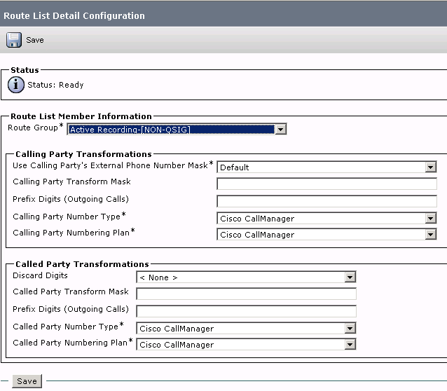
Click Add Route Group.
-
In the Route List Detail Configuration window, in the Route List Member Information area, from the Route Group list, select the Route Group that you created.
-
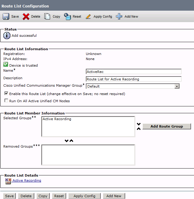
Click Save. The Status appears as Successful and the newly created Route List appears in the Route List Member Information list and the Route List Details area.
-
Click Reset.
-
Click Reset.
-
Click Close.
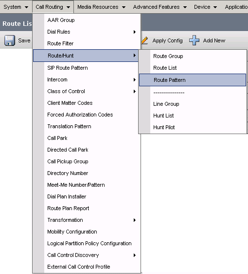
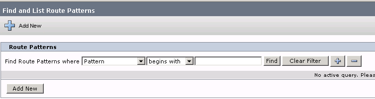
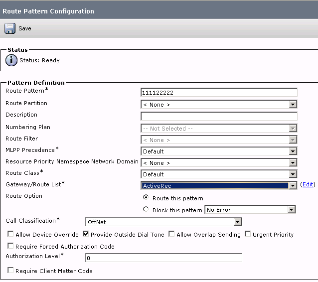
Configure a New Route Pattern
Define a new Route Pattern based on the Device Number for the Recorder that you created previously. The new Route Pattern points to the Recorder Route List.
-
Go to Call Routing > Route/Hunt > Route Pattern.
-
In the Find and List Route Groups window, click Add New.
-
In the Pattern Definition area, in the Route Pattern field, enter the Recording Destination Address from the Configure the Recording Profile section.
-
From the Gateway/Route List arrow, select the Route List.
-
Click Save.
-
In the Windows Internet Browser message window, click OK.
Network Based Recording (NBR) Definition
Cisco Network Based Recording (NBR) uses a recording enabled gateway to fork the RTP media. This enables the recording priority of a Recording-enabled Gateway (if available).
-
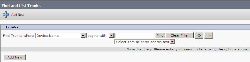
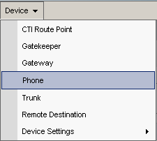
Go to Device > Trunk.
-
In the Find and List Trunks window, search for the SIP trunk of the recording-enabled gateway.
-
Select the trunk.
-
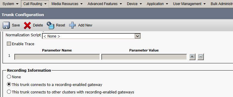
On the Trunk Configuration window, scroll down to the Recording Information area.
-
In the Recording Information area, click the This trunk connects to a recording-enabled gateway option:
-
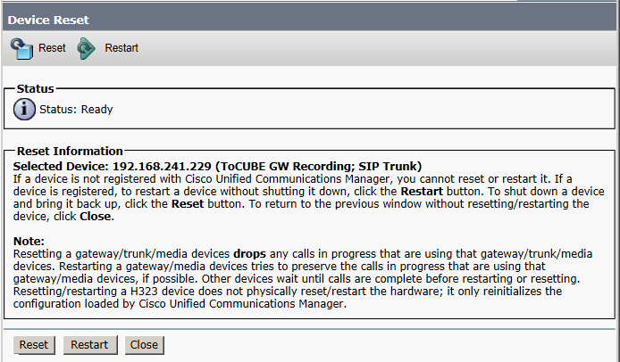
Click Save.
-
Click Reset to reset the trunk.


On the recording-enabled gateway, configure:
|
Parameter |
Description |
action |
|---|---|---|
|
source-address |
IP address of the recording-enabled gateway |
Type: var(--codeSnippetCopyLabel)
|
|
provider xmf |
Add a config command with the URL of each Publisher and Subscriber/s. For each Publisher/Subscriber, increase the remote-url number. |
Type: var(--codeSnippetCopyLabel)
|
For Cisco deployments with CVP and CUSP where inbound calls are not routed through direct SIP trunks between CUCM and the Gateways/CUBE(s)/vCUBE(s), all communication between CUBE/vCUBE and CUCM goes via a single SIP trunk to CVP/CUSP.
Before sending the recording requests, the CUCM needs to know which CUBE/vCUBE the call is coming from. It does this by sending the request back to the destination IP of the incoming SIP trunk that was used for the call.
CUCM needs a way to know from which CUBE/vCUBE the call is coming, so that it knows where to send the recording requests. This is achieved by sending the request back to the destination IP of the incoming SIP trunk that was used for the call. However, if CUCM sends the API request back to CUSP nothing will happen. To work around this limitation in environments with CVP/CUSP, implement this CUCM configuration.
Associate Recording Profile
You now need to associate the Recording Profile with the recorded Device Number. You also set the recording method here.
Cisco IP Phones have multiple line appearances![]() Physical phones often have multiple line appearances on them. Each number displayed on the physical phone screen is the DN associated with the device. Each device can have more than one line appearance. A line appearance is the linkage of a line to a device.
Multiple Line Appearance is an important factor to consider for system mapping.. Each line appearance in a phone device can be configured separately in the CUCM administration with its own recording method.
Physical phones often have multiple line appearances on them. Each number displayed on the physical phone screen is the DN associated with the device. Each device can have more than one line appearance. A line appearance is the linkage of a line to a device.
Multiple Line Appearance is an important factor to consider for system mapping.. Each line appearance in a phone device can be configured separately in the CUCM administration with its own recording method.
JTAPI active recording requires the CUCM to be set to Automatic Call Recording Enabled.
Select the Cisco recording method:
-
For JTAPI active recording, select Automatic Call Recording Enabled.
-
For no recording, select Call Recording Disabled.
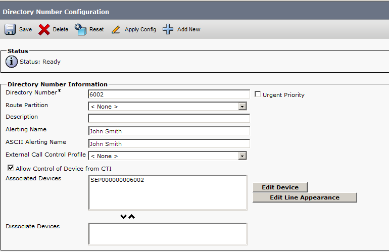
To associate the Recording Profile with the recorded Device Number:
-
Verify that the new Route Pattern is configured.
-
Go to Device > Phone.
-
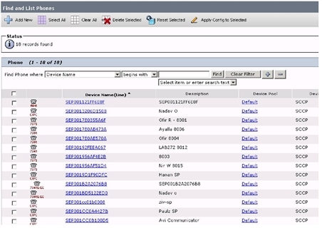
The Find and List Phones window appears. Search for the phones that you want to record and click Find.
-
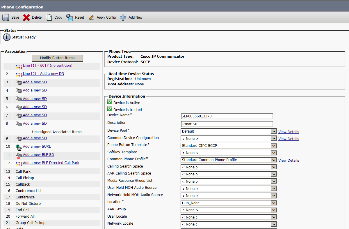
On the Phone Configuration window, in the Association area, click the phone line link.
-
On the Directory Number Configuration window, scroll down to Line 1 on Device area.
-
From the Recording Option list, select the required enabled option. You can verify that these have been correctly configured in the JTAPIMonitor application.
The Recording Options are:
-
Call Recording Disabled: select this if no recording is permitted.
-
Automatic Call Recording Enabled: select this for all JTAPI active recording
-
Device Invoked Call Recording Enabled: not currently in use.
-
-
From the Recording Profile list, select the Recording Profile defined in Configure the Recording Profile.
-
From the Recording Media Source list, select Gateway Preferred if you want to prioritize recording through a Recording-enabled Gateway (if available) using the Network-Based-Recording feature.
-
In the Multiple Call/Call Waiting Settings on Device area, set the Busy Trigger value to equal to the Maximum number of calls parameter.
-
Click Save.

Phone Notification Tone Definition
Cisco’s active recording provides you with an optional feature, enabling you to configure the notification tones on the phone itself. Notification tones can be configured on either a system-wide level or a device level.
Cisco Monitoring and NiCE CXone monitoring have two completely different meanings. The monitoring referred to here is Cisco monitoring.
An IP phone can be monitored and recorded at the same time. A user can be notified that they are being monitored and/or recorded by notification tones (beep tones).
In Cisco’s IP Phone-based Active Recording, the Monitoring tone and the Recording tone have different sounds and can be enabled or disabled independently. If both monitoring and recording are being used and the phone is configured to give notifications, the Recording tone always takes precedence over the Monitoring tone.
Define notification tones on both a system-wide level or a device level.
To define notification tones on a system-wide level:
-
Verify that you have associated the Recording Profile and selected the recording method.
-
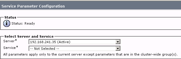
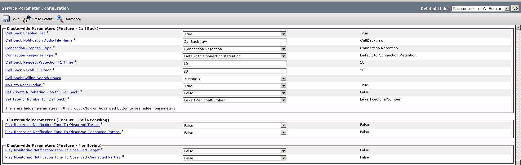
Go to System > Service Parameters.
-
In the Service Parameters Configuration window, in the Select Server and Service area, from the Server drop-down arrow, select the server. The Service field of the selected server appears.
-
From the Service drop-down arrow, select Cisco CallManager (Active).
-
In the Service Parameter Configuration window, scroll down to the Clusterwide Parameters (Feature - Call Recording) area.
-
To play the notification tone to the observed target i.e. the agent, click the Play Recording Notification Tone to Observed Target arrow and click True.
-
To play the notification tone to the observed connected target i.e. the customer, click the Play Recording Notification Tone to Observed Connected Parties arrow and click True.
-
Click Save. The Status appears as Update successful.
If the customer requires notification tones on a device level, configure this. It also enables you to define recording tones, recording volume, the remote volume and the recording tone duration.
This section is relevant only to Cisco IP phones that support recording (the feature is not relevant to Cisco IP Communicator phones. Changing the tone for the Cisco IP Communicator can only be done at the system level. Changing the notification tones at the device level for Cisco IP phones will override the selection you made at the system level.
To define notification tones on a device level:
-
Verify that you have associated the Recording Profile and selected the recording method.
-
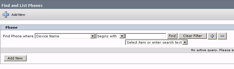
Go to Device > Phone.
The Find and List Phones window appears.
-
Search for the phones that you want to record and click Find.
-
On the Find and List Phones page, click the phone link.
-
On the Phone Configuration window, scroll down to the Product Specific Configuration Layout area. The Recording Tone options are relevant only for Cisco IP phones.
-
From the Recording Tone drop-down list, select the recording tone option.
-
In the Recording Tone Local Volume field, enter the local volume.
-
In the Recording Tone Remote Volume field, enter the remote volume.
-
In the Recording Tone Duration Field, enter the recording tone duration.
-
Click Save.
-
In the Windows Internet Browser message window, click OK.
The Status appears as Update successful.
-
Click Apply Config. The Apply Configuration window appears.
-
Click OK. For each phone that you need to set the notification tones on a device level, repeat the procedure.
(Optional) Enable NiCE Business Data Display
Before certain business data fields can display in Real-Time Third Party Telephony Recording (Multi-ACD), the Display Internal Caller ID and Alerting Name CUCM fields should be configured:
|
CUCM Field |
JTAPI Business Data Field |
|---|---|
|
Display Internal Caller ID |
CurrentCalledName CurrentCallingName |
|
Alerting Name |
CalledName |
To configure the Display Internal Caller ID and Alerting Name fields:
-
Go to Device > Phone.
The Find and List Phones window appears.
-
Search for the phones and click Find.
-
On the Find and List Phones page, click the phone link.
-
In the Phone Configuration window, in the Association area, select the line.
-
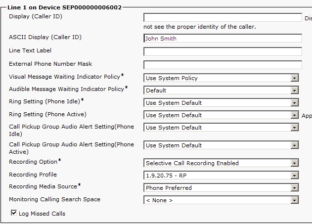
In the Directory Number Configuration window, under Directory Number Information, in the Alerting Name field, enter the Alerting Name
Call to Actions. -
Scroll down to the Line.
-
In the Display (Caller ID) field, enter the name.
In the example, this is John Smith.