This topic provides guidelines for configuring Avaya TSAPI interface with SIPREC and DMCC for NiCE CXone Real-Time Third Party Telephony Recording (Multi-ACD).
The supported Avaya AES TSAPI versions are 8.1.3, 10.1, 10.2.
Avaya site engineer is responsible for all procedures in the Avaya environment. The procedures described in this section are by recommendation only!
Follow these steps to set up the Avaya TSAPI interface with SIPREC and DMCC.
Step 1: Prepare Avaya AES TSAPI Environment
Step 2:Prepare Avaya AES DMCC Environment
Step 3: Prepare Session Border Controllers (SBCs) to integrate with Real-Time Third Party Telephony Recording (Multi-ACD):
Step 4: Download and save the Essential Data for 3rd Party Connectivity Config in NiCE CXone Excel file. You will be required to fill in essential information as you proceed. Once you have finished entering all the necessary details and prepared your environment for Real-Time Third Party Telephony Recording (Multi-ACD), you must submit the Excel file to your NiCE Professional Services representative.
Prepare Avaya AES TSAPI Environment
You must configure the Avaya AES TSAPI Server before you configure Real-Time Third Party Telephony Recording (Multi-ACD).
The supported Avaya AES TSAPI versions are 8.1.3, 10.1, 10.2.
Perform these steps to prepare the Avaya AES TSAPI environment:
Step 1: Verify the TSAPI License and Status
Step 2: Prepare the AES Environment
Step 5: Create a Secure Connection Using VPN
Step 1: Verify the TSAPI License and Status
Before configuring the Avaya TSAPI interface, you must verify that the Avaya TSAPI Service is running, and that the license is valid.
To verify the TSAPI Service and status:
-
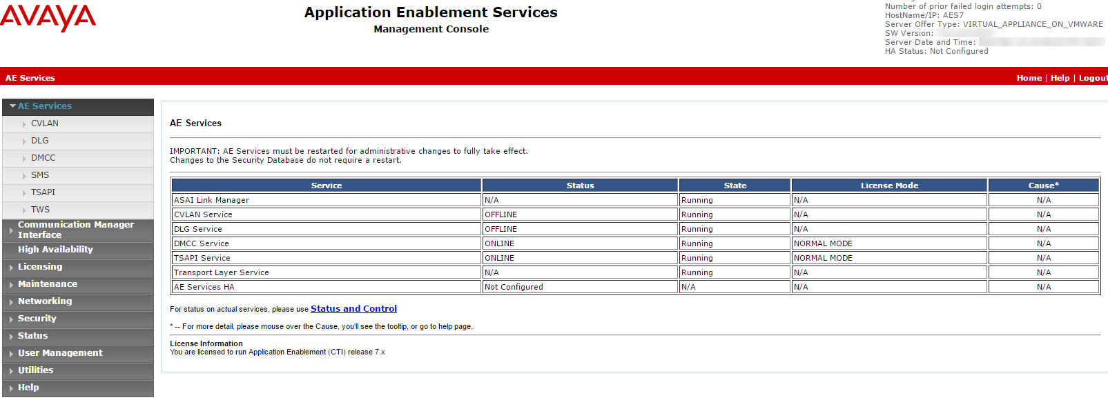
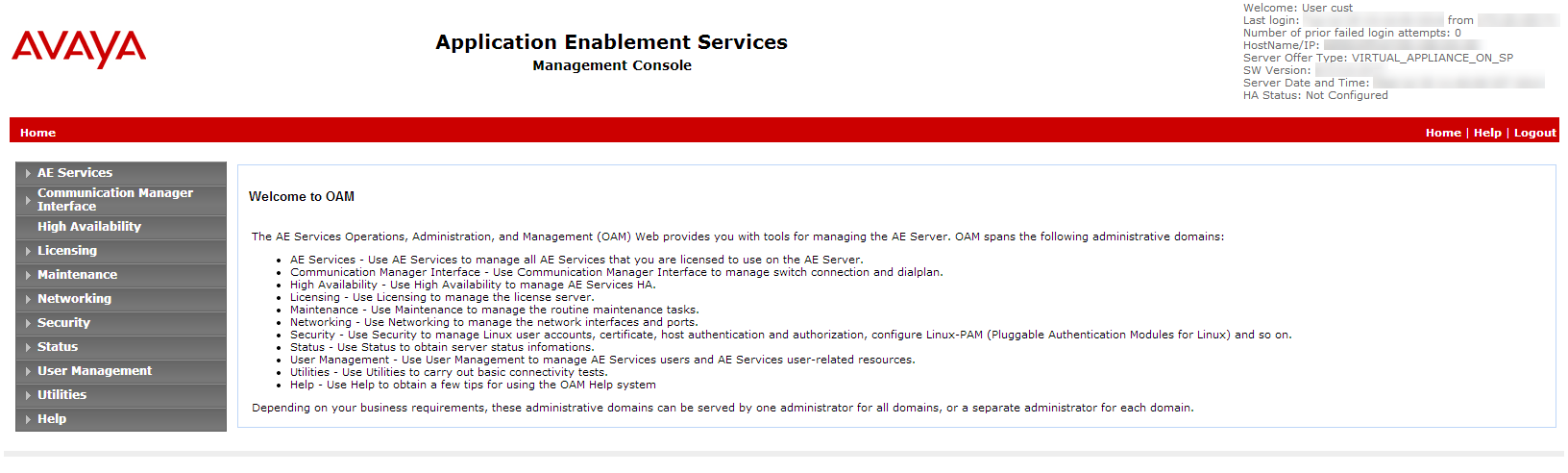
Log in to the AES Server. The Application Enablement Services page appears.
-
From the menu, select AE Services.
-
Verify:
-
The TSAPI Service Status column is Online and that the State is Running.
-
The Licensed Mode column shows Normal Mode.
-
Step 2: Prepare the AES Environment
An Avaya site engineer is responsible for all procedures in the Avaya environment. These procedures are recommendations and guidelines only!
In an AES environment, the AES administrator must prepare the AES-CTI link connections.
To configure the switch on the AES (general guidelines):
-
Navigate to the AES webpage and login.
-
Enter your Username and Password. Click Login. The Home page appears.
-
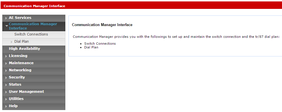
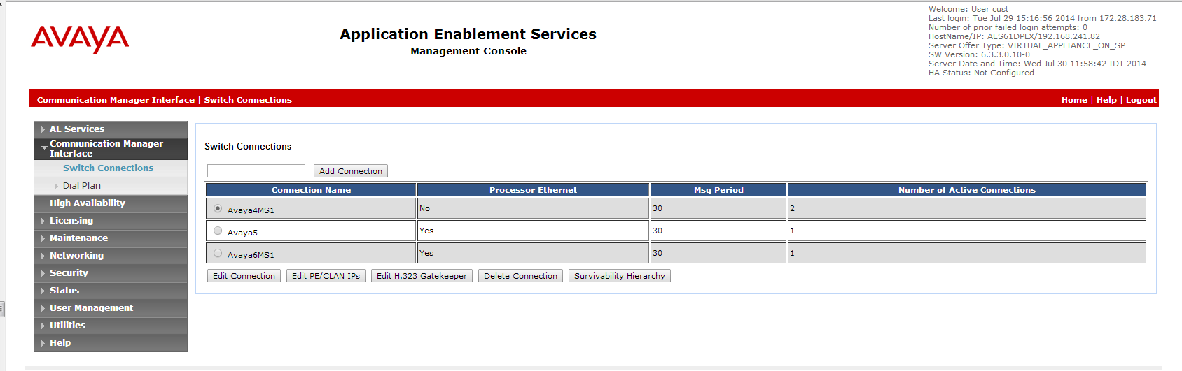
From the menu, click Communication Manager Interface.
-
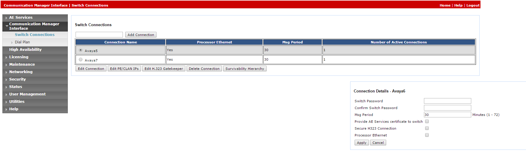
Select Switch Connections.
-
In the Switch Connections window, in the field add the switch name and click Add Connection. The Connection Details window for the new switch appears.
-
In the Switch Password field, enter the switch password. The switch password must be between 12 - 16 alphanumeric characters and identical to the password assigned to the AES service in the Communication Manager.
-
In the Confirm Switch Password field, enter the switch password again.
-
If your Communication Manager supports Processor Ethernet, select Processor Ethernet.
-
Click Apply. The Switch Connections window reappears.
-
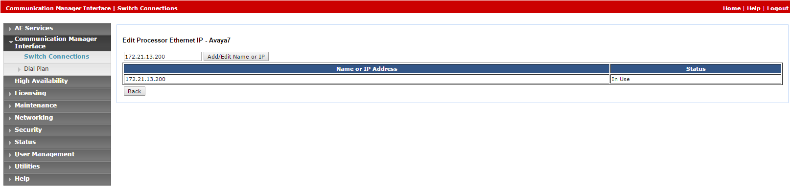
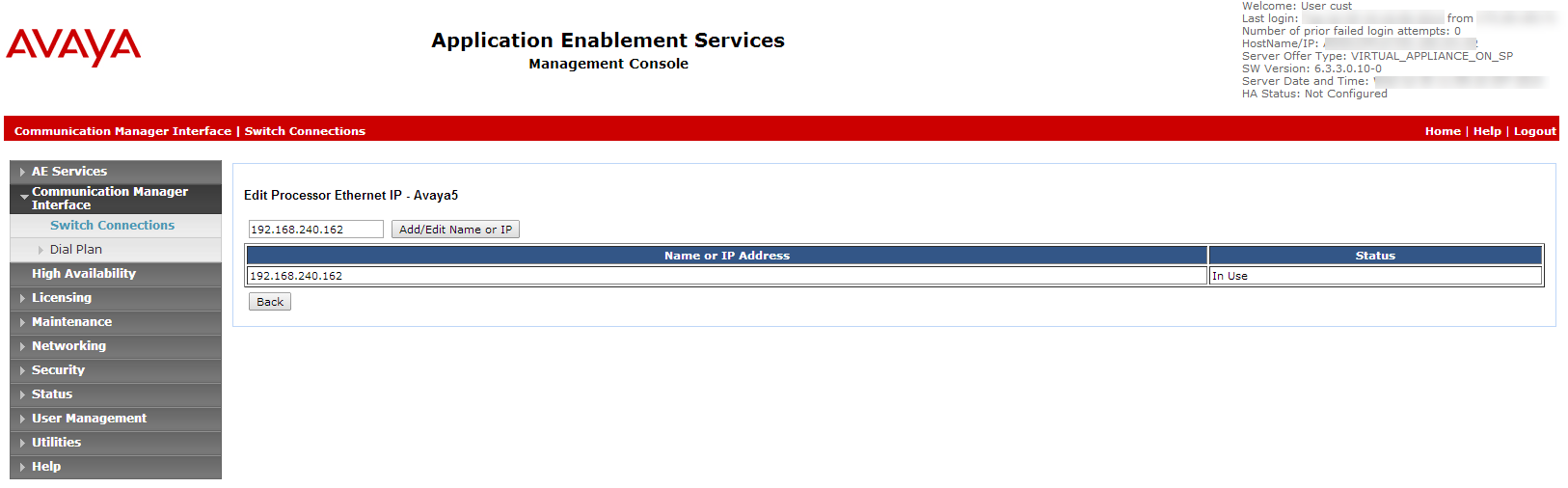
-
Click Edit PE/CLAN IPs. The Edit Processor Ethernet IP window appears.
-
In the field provided, add the IP address of the Processor Ethernet/CLAN board, then click Add/Edit Name or IP.
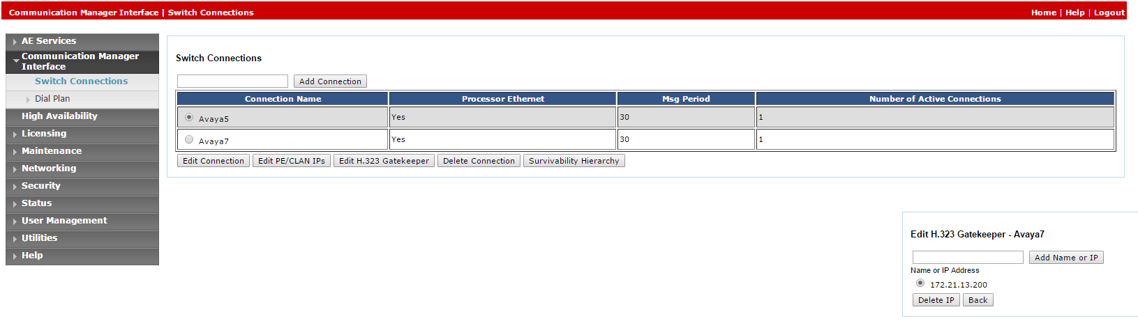
-
In the AES menu, click Switch Connections to return to the Switch Connections window.
-
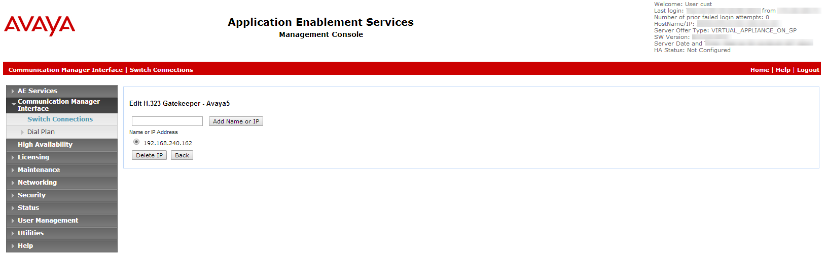
Click Edit H.323 Gatekeeper. The Edit H.323 Gatekeeper window appears.
-
In the field provided, enter the IP address of one of the Processor Ethernet/CLAN boards, and click Add Name or IP. Repeat this step for all Processor Ethernet/CLAN boards.

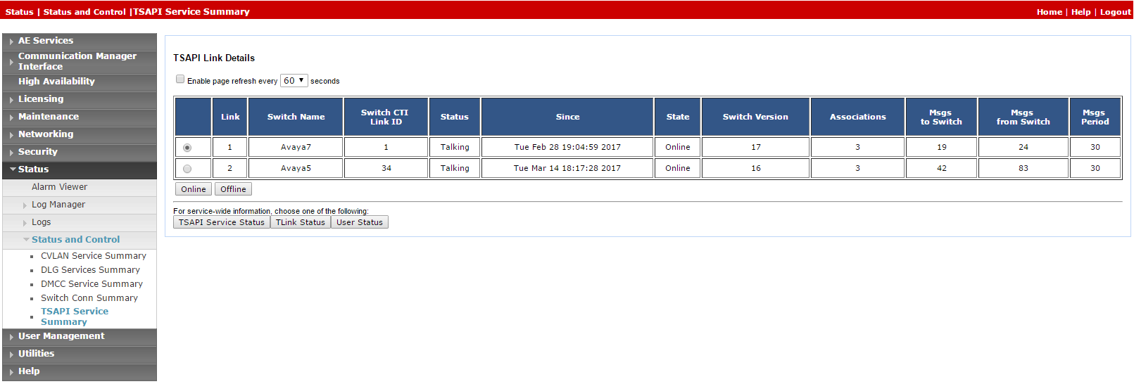
After the CTI link is configured, the administrator should verify that the AES-CTI link connection is active and in a Talking state.
To verify the CTI link:
-
From the AES webpage, select Status > Status and Control > TSAPI Service Summary.
-
Check the Status is set for Talking for the relevant AES-CTI link connection.
Step 3: Add a User
The user must be added to the system via the webpage.
This procedure must be performed together with an Avaya administrator. The AES administrator must first prepare the AES-CTI link connection.
At the end of this step, you are required to provide to NiCE Professional Services:
-
User credentials.
To add a user:
-
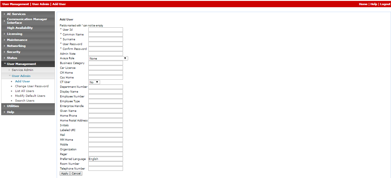
On the AE Services menu, navigate to User Management > User Admin and click Add User.
-
In the Add User window, configure the mandatory fields:
-
User Id
-
Common Name
-
Surname
-
User Password
-
Confirm Password
-
Change the CT User setting to Yes.
-
-
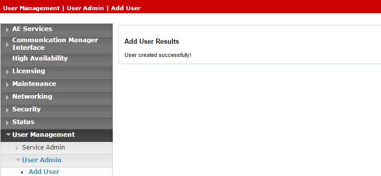
Click Apply to save the information.
-
Save these user credentials in the Excel file. Once you have finished entering all the necessary details and prepared your environment, submit the Excel file to NiCE Professional Services.
-
Verify that the User created successfully message appears in the Add User Results window.
-
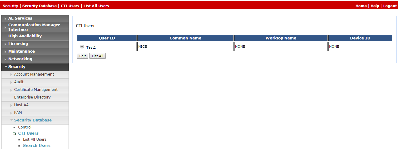
Provide unrestricted monitoring for all devices to user:
-
On the AE Services menu, expand Security > Security Database > CTI Users and click Search Users.
-
In the Search Users window, search for the user created previously.
-
Click Search. The new user appears.
-
Click Edit.
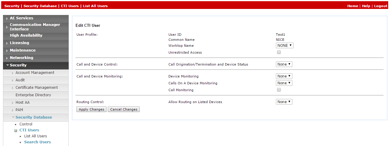
-
In the Edit CTI User window, in the User Profile area, select Unrestricted Access.
-
Click Apply Changes.
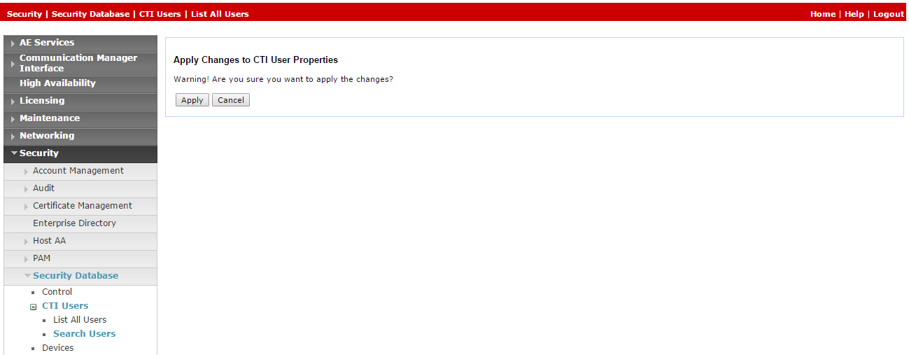
-
In the Apply Changes to CTI User Properties, click Apply.
-

Step 4: Verify the Tlink
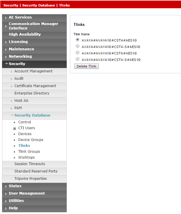
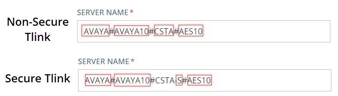
In the CTI Connection TSAPI configuration, the Server Name parameter uses the Tlink value.
At the end of this step, you are required to provide to NiCE Professional Services:
-
Tlink name
To verify the Tlink:
-
In the AES webpage, select Security > Security Database > Tlinks.
The list of Tlinks appears in the Tlink Name column. If your site uses more than one Tlink, make sure you choose the correct Tlink, according to the switch name.
The Tlink consists of these segments:
-
AVAYA - Vendor
-
# - Separator
-
AVAYA10 - Switch / Connection Name (as defined in Communication Manager Interface> Switch Connections)
-
CSTA/CSTA-S - Non-Secure / Secure Portal
-
AES10 - AES Server Name
-
-
Save the correct Tlink name in the Excel file. Once you have finished entering all the necessary details and prepared your environment, submit the Excel file to NiCE Professional Services.
-
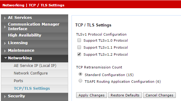
If using the secured Tlink, verify that the TLS version is configured in the AES. Navigate to Networking > TCP/TLS Settings.
-
By default, only Support TLSv1.2 Protocol is enabled. TLSv1.2 Protocol is supported as a sole security protocol.
-
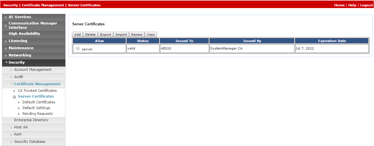
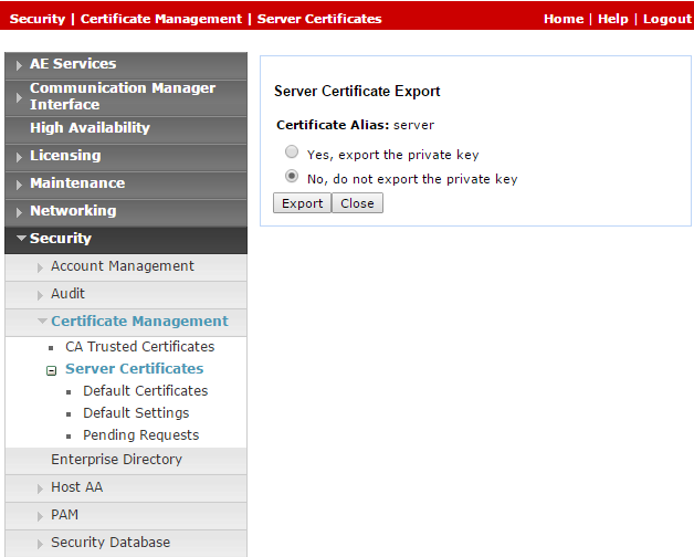
Since default certificates are no longer provided, the Avaya site engineer must generate the relevant certificate and upload it to the Avaya telephony system in NiCE CXone. Navigate to Security > Certificate Management > Server Certificates.
-
In the Server Certificates window, in the Alias column, select the certificate and click Export.
-
In the Server Certificate Export window, verify that No, do not export the private key is selected and click Export.
-
Upload this exported certificate to the Avaya telephony system in NiCE CXone.
Step 5: Create a Secure Connection Using VPN
This step must be performed only in coordination with NiCE Professional Services.
At the end this step, by completing the form in the Essential Data for 3rd Party Connectivity Config in NiCE CXone Excel file, you will provide the necessary details to NiCE Professional Services, who will aid you in establishing a secure VPN connection with NiCE CXone.
SIPREC environments only are required to complete additional information in the form, so that SBC can establish a connection between SIPREC and NiCE CXone.
-
NiCE Professional Services will provide you with the VPN connect form.
-
Fill out the provided form with details of your side and the necessary information for Real-Time Third Party Telephony Recording (Multi-ACD).
-
NiCE Professional Services will coordinate with NiCE CXone teams to ensure all fields are appropriately filled out.
-
Both parties must agree on the form and details.
-
-
NiCE Professional Services will schedule a collaborative call:
- To agree on the form and provided details with Real-Time Third Party Telephony Recording (Multi-ACD).
-
With NiCE CXone teams for VPN provisioning.
-
You will set up two VPNs: one for resiliency and one for failover.
-
Configure routing by setting up BGP over VPN with Real-Time Third Party Telephony Recording (Multi-ACD) firewalls or create static routes to the provided IP addresses.
-
Configure NAT. NAT your endpoint behind a public IP, either advertised via BGP or using static routing.
-
Configure firewall settings:
-
Allow inbound traffic from the provided IP addresses (2) into the CTI Endpoint.
-
Open the required ports. See Ports and Protocols by Application for more information.
-
For High Availability environments, the ports mentioned above in step b must be open for all servers, active and standby.
-
-
NiCE Professional Services will coordinate with NiCE CXone teams to:
-
Ensure the VPN form is correctly filled out.
-
Schedule a time with NiCE CXone teams for VPN provisioning and routing setup.
-
Test VPN tunnel, routing, and connectivity.
-
Prepare Avaya AES DMCC Environment
This section describes how to prepare the Avaya Device Media Call Control (DMCC) environment for Real-Time Third Party Telephony Recording (Multi-ACD).
The supported Avaya AES DMCC versions are 8.1.3, 10.1, and 10.2.
Avaya site engineer is responsible for all procedures in the Avaya environment. The procedures described in this section are by recommendation only!
For comprehensive information about configuring the Avaya switch, see the Avaya documentation.
Workflow
Use this workflow to set up Avaya DMCC active recording with Real-Time Third Party Telephony Recording (Multi-ACD).
Before beginning this workflow, you must ensure that site components are configured.
Step 1: Configure Virtual Extensions to Capture Audio
Step 2: Configure SRTP
Step 3: Optional: Configure Two DMCC Observers on a Single Tenant
Step 4: Prepare information for NiCE Professional Services
Before You Begin
Before integrating the Avaya DMCC environment with Engagement Hub (Multi-ACD/Open), gather the required information and enter it in the Essential Data for 3rd Party Connectivity Config in NiCE CXone Excel file you downloaded. Once you have finished entering all the necessary details and prepared your environment, submit the Excel file to NiCE Professional Services.
Configure Virtual Extensions to Capture Audio
Use these procedures to prepare the Avaya Communication Manager for a site using virtual extensions for audio capture.
When using virtual extensions to capture your audio, verify you have enough licenses for the NiCE CTI.
-
Log in to the AES Server. The Application Enablement Services page appears.
-
From the menu, select Licensing > WebLM Server Access.
-
Log in to WebLM Server.
-
Select Licensed products > Application Enablement from the panel on the left, and verify that sufficient licenses are defined for DMCC DMC.
Before the DMCC Server can register the emulated (virtual) extensions on the Media Gateway, define the extensions on the switch.
Each virtual extension must be separately defined and requires a DMCC license. Make sure the total number of DMCC licenses match the maximum number of agents operating concurrently. However, it is recommended to maintain DMCC licenses at least 20% above the maximum call volume.
When your site is configured for Single Step Conference, you must define the virtual extensions on the AES in the same group as the extensions observed via Single Step Conference. Otherwise, the user will be granted unrestricted access to the security database.
To define the virtual extensions for recording on the switch:
-
On the switch, open a console window and type this:
-
Extension Type: 4624
ExtensionType 4624 represents all soft phones.
-
IP Softphone: Y (Yes)
-
Security Code: This is the password for the extension. It will be used in the Device Password field when configuring the Avaya DMCC interface under Third Party Telephony in NiCE CXone. The Security Code must be consistent for all virtual extensions.
-
The Avaya AES Server supports up to 16 simultaneous C-LAN connections. This allows the AES Server to provide load balancing across multiple connections and a C-LAN failover mechanism.
You configure the symbolic name, or Connection Name, on the Avaya AES Server. The symbolic name represents multiple C-LANs on the Avaya Media Gateways. This allows the recording system to implement redundancy and load sharing over multiple C-LANs by communicating with the symbolic name. Multiple C-LANs are required in implementations of over 300 Avaya DMCC channels.
The symbolic name is the Connection Name on the AES, and is case sensitive.
To configure the symbolic name:
-
From the AES webpage, select Communication Manager Interface > Switch Connections.
-
Select the required Connection Name and click Edit PE/CLAN IPs.
-
Enter the host name or IP address of the C-LAN or/and PE for AES connectivity, and then click Add/Edit Name or IP. Repeat for each C-LAN or PE attached to this connection.
-
In the Switch Connections window, click Edit H.323 Gatekeeper.
To use the symbolic name feature, the H.323 gatekeeper must be specified. The C-LAN configuration alone is not sufficient. The H.323 IP list can be different from the C-LAN IP list.
-
Select the required Name or IP Address, or type in the host name or IP address of the H.323 Gatekeeper and click Add Name or IP.
-
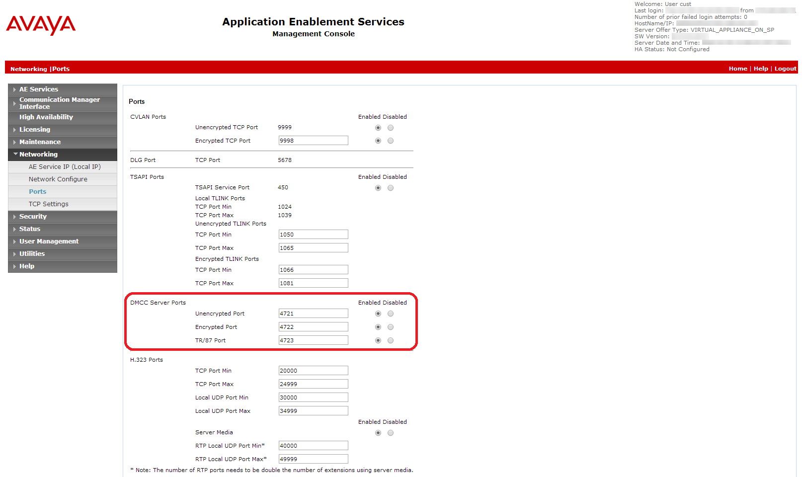
Select Networking > Ports.
-
Ensure that the DMCC Server port is enabled.
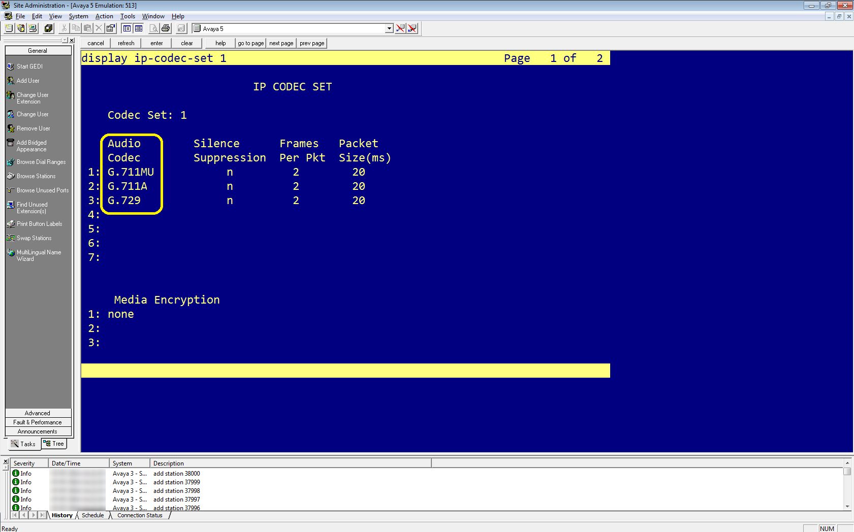
The codec set defined in Real-Time Third Party Telephony Recording (Multi-ACD) must match the codec set defined on the switch.
-
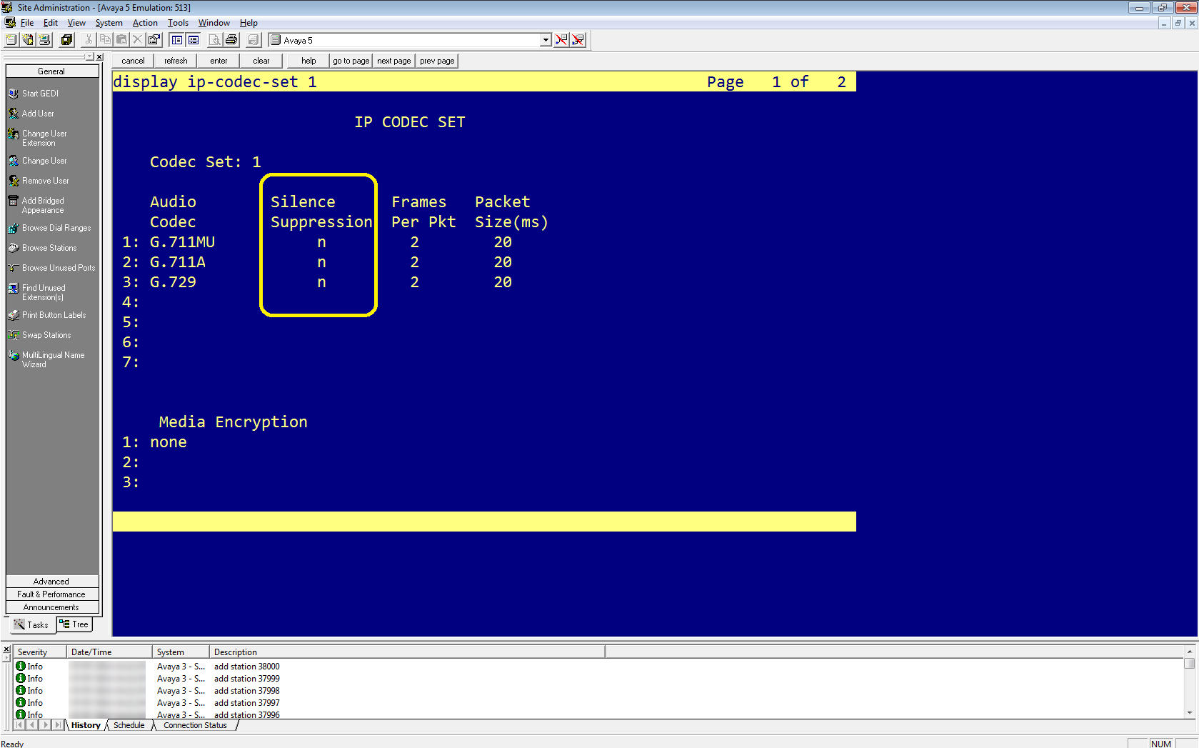
In Avaya Site Administration, enter display ip-codec-set <n> where <n> is the codec set associated with the IP network region of the extensions that you need to observe.
-
In the Audio Codec column, review the list of compression types. These are the codecs that the switch allows.
Make sure that the CodecList you define in Real-Time Third Party Telephony Recording (Multi-ACD) contains at least one of the compression types defined here.
-
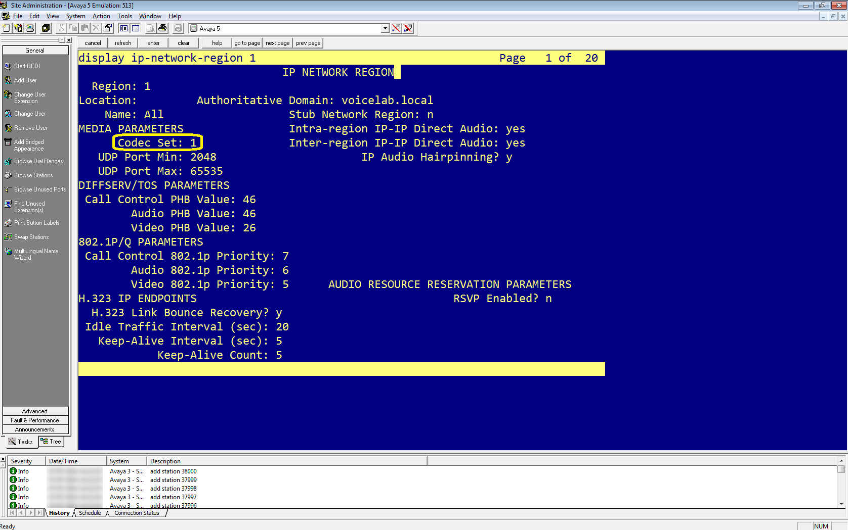
Enter display ip-network-region <n> where <n> is the network region of the extensions that you need to observe.
-
Verify that the defined Codec Set is the ip-codec-set you confirmed above.
Verify that the silence suppression feature is enabled on Avaya Media Server for audio codecs. This conserves bandwidth by not transmitting audio packets during periods of silence. Silence suppression may cause audio clipping.
-
In Avaya Site Administration, enter the display ip-codec-set <n> command, where <n> is the number of the codec set associated with the IP network region of the extensions that you need to observe.
-
In the IP Codec Set window, in the Codec Set section, for each codec listed you can set in the Silence Suppression column:
-
Enable silence suppression, define Silence Suppression as y.
-
Disable silence suppression, define Silence Suppression as n.
-
-
Press Esc and then e to submit your changes.
Configure SRTP
Use these procedures when your site requires SRTP configuration.
-
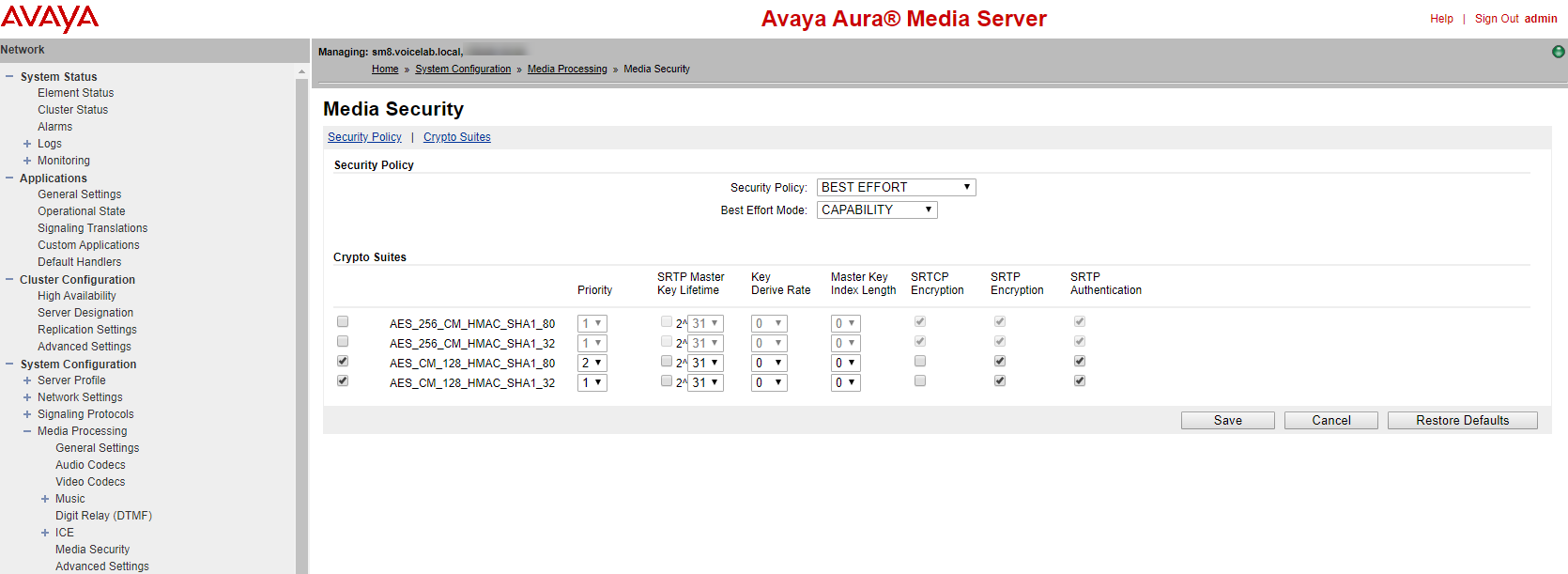
Log in to the Avaya Aura Media server.
-
Under the System Configuration menu, go to Media Processing > Media Security.
-
Verify that:
-
Security Policy is set to BEST EFFORT.
-
Best Effort Mode is set to CAPABILITY.
-
-
Under Crypto Suites, enable:
-
AES_CM_128_HMAC_SHA1_80
-
AES_CM_128_HMAC_SHA1_32
-
-
For each of them, select SRTP encryption and SRTP Authentication.
-
Go to Configuring Avaya Switch Encryption for the IP Network Region.
SRTP encryption is configured on two levels: the signaling (H.323) and the media stream (SRTP).
This section describes how to enable SRTP and signaling encryption on Avaya Communication Manager.
At the end of this procedure, you are required to provide to NiCE Professional Services:
-
Encryption used on site: HMAC32 or HMAC80.
To configure encryption:
-
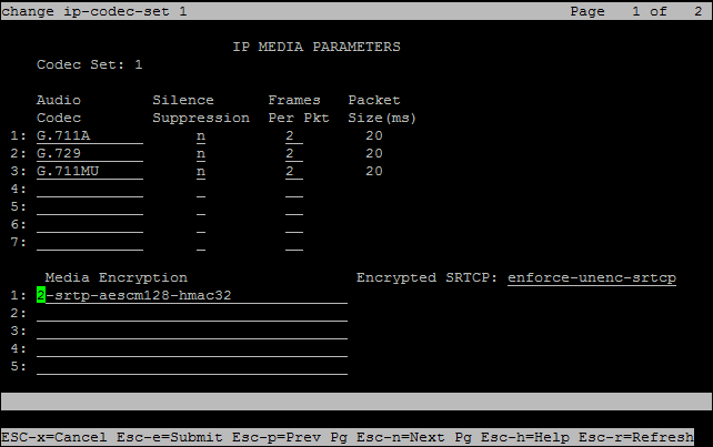
In Avaya Site Administration, enter the display ip-codec-set <n> command, where <n> is the codec-set associated with the IP network region of the extensions that you need to observe.
-
Verify if the site has:
-
Avaya Media Servers with G Series gateway/s. aes can be supported only with G-series gateways.
-
Avaya Media Servers, use either 2-srtp-aescm128-hmac32 or 1-srtp-aescm128-hmac80.
-
-
In the IP Codec Set screen, in the Media Encryption section, enter one or more of the Media Encryption types.
-
2-srtp-aescm128-hmac32
-
1-srtp-aescm128-hmac80
-
aes - not supported if using Avaya Media Server
The Avaya site engineer must inform NiCE Professional Services which encryption is used on site: HMAC32 or HMAC80.
Save the encryption information in the Excel file. Once you have finished entering all the necessary details and prepared your environment, submit the Excel file to NiCE Professional Services.
-
-
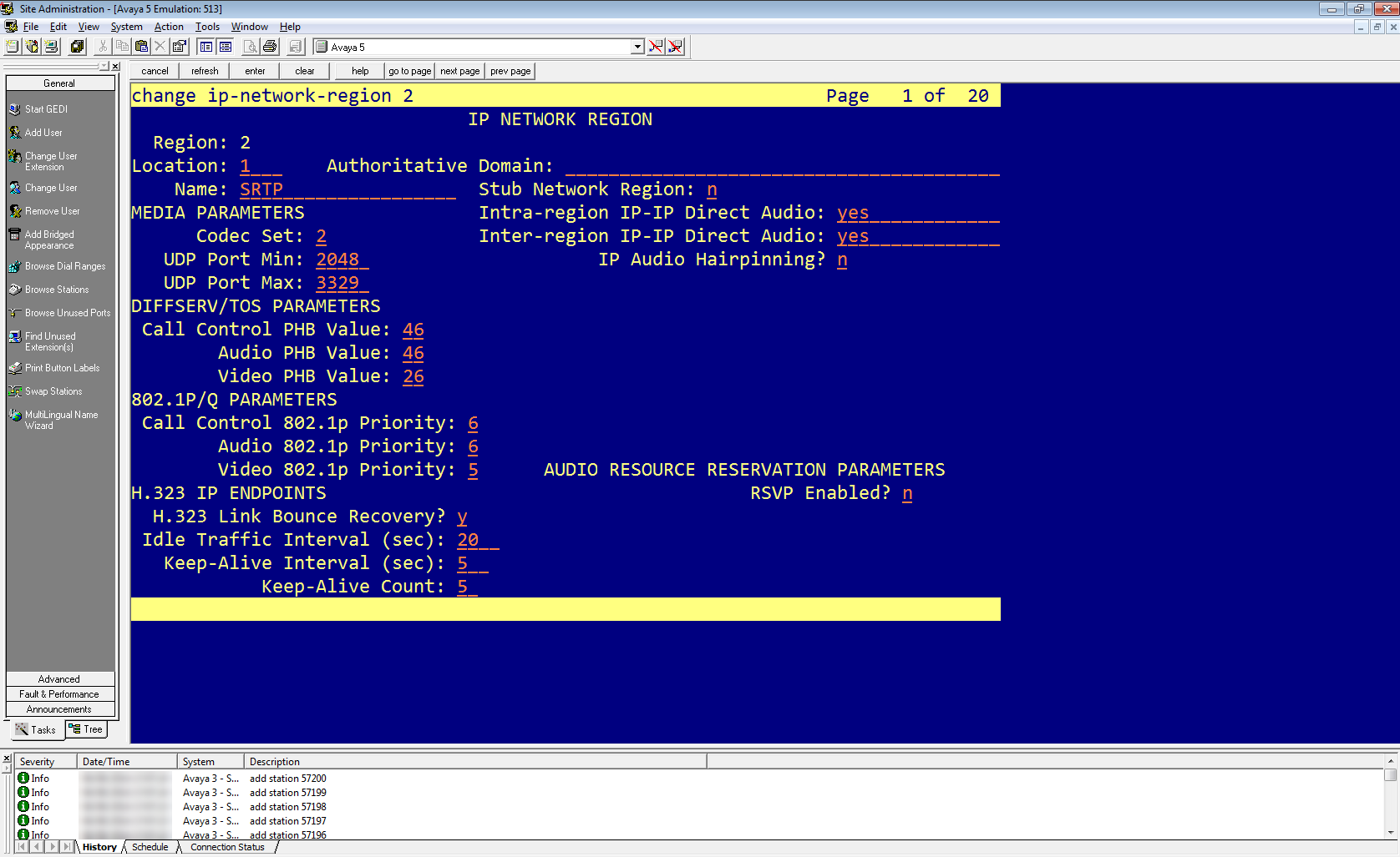
In Avaya Site Administration, enter the display ip-network-region <n> command, where <n> is the network region of the extensions that you need to observe.
-
In the network region, enter the IP Codec Set you edited previously.
-
When you configure CLAN/Medpro: In the Network Region, enter the region you configured for encryption. In the example in this procedure, to enable SRTP in the Network Region, enter 2.
Optional: Configure Two DMCC Observers on a Single Tenant
NiCE CXone supports using two DMCC Observers in one tenant![]() High-level organizational grouping used to manage technical support, billing, and global settings for your NiCE CXone system.. Use this setup when you need greater scalability or redundancy across two separate Avaya systems.
High-level organizational grouping used to manage technical support, billing, and global settings for your NiCE CXone system.. Use this setup when you need greater scalability or redundancy across two separate Avaya systems.
To support two DMCC Observers on a single NiCE CXone tenant, the environment must be modeled as two fully independent Avaya telephony systems:
-
Telephony System A
-
AES Server A connected to Communication Manager A (CM A)
-
Dedicated virtual extension range (VE Set A)
-
-
Telephony System B
-
AES Server B connected to Communication Manager B (CM B)
-
Dedicated virtual extension range (VE Set B)
-
Both systems must use different AES servers, different Communication Managers, and non‑overlapping DMCC virtual extension ranges. Each AES server may use local HA (Active–Standby).
-
Complete all steps required to prepare the Avaya AES DMCC environment for a single telephony system.
-
Make sure that you have:
-
Two independent Communication Managers (CM A and CM B)
-
Two AES servers (AES A and AES B) with:
-
Valid DMCC licenses
-
CTI user and Tlink
-
DMCC ports enabled (secure or non-secure or both)
-
-
Two unique virtual extension ranges (one per telephony system)
-
-
Verify that network or security teams or both are ready to configure:
-
VPN and routing to both AES servers
-
SBC settings for both Observers
-
DNS (for example, Route 53) for Observer FQDNs
-
For each AES/CM pair, NiCE Professional Services will set up two matching Avaya DMCC telephony entries in NiCE CXone.
Run the Prepare Avaya AES DMCC Environment workflow twice, once for each telephony system, with these constraints:
-
Configure AES A and AES B independently:
-
Separate Tlinks (one per AES).
-
Separate CTI users (or distinct credentials) if required by your security policy.
-
Verify DMCC ports on each AES (secure and/or non-secure).
-
-
Define the Virtual Extensions for Recording:
-
On CM A, create a VE range dedicated to Telephony System A.
-
On CM B, create a separate VE range dedicated to Telephony System B.
-
Do not reuse the same VE numbers between CM A and CM B.
-
-
Verify and document Codec Set and Encryption details.
The SBC connects to the DMCC Observers over SIP. By default, the following ports are used on the NiCE CXone side:
-
Non-secure (TCP):
-
Observer 1: 5060
-
Observer 2: 5062
-
-
Secure (TLS):
-
Observer 1: 5061
-
Observer 2: 5063
-
-
Define two separate SIP destinations (or IP Groups or Session Recording Servers) that correspond to the two DMCC Observers, including:
-
Observer FQDN or IP
-
Port (5060/5062 or 5061/5063, depending on security)
-
Transport (TCP or TLS)
-
-
For each recording rule or session recording configuration on the SBC:
-
The Recorder, SRS, or Recording Server points to the correct Observer FQDN and port for the relevant telephony system.
-
If you are using secure SIP (TLS), the appropriate TLS context and certificates are configured as described in the SBC sections in this topic.
-
Each DMCC Observer must be resolvable via DNS and must have its own DNS record. Don't reuse the same FQDN for both Observers.
-
Create a DNS record for Observer 1:
-
Type: A or CNAME
-
FQDN: for example,
observer1.<your-domain> -
Target: the Observer 1 IP address.
-
-
Create a DNS record for Observer 2:
-
Type: A or CNAME
-
FQDN: for example,
observer2.<your-domain> -
Target: the Observer 2 IP address.
-
-
If you use AWS Route 53 for DNS, create the corresponding records there.
NiCE Professional Services will reference these FQDNs in the NiCE CXone configuration.
Because you are using two AES servers and two DMCC Observers, the network paths must allow all combinations of Observer AES traffic.
-
From the customer side, configure VPN routing so that:
-
Observer 1 can reach AES A and AES B.
-
Observer 2 can reach AES A and AES B.
-
-
Configure the following firewall rules:
-
Allow inbound and outbound SIP and RTP/SRTP traffic between:
-
Each Observer IP (or subnet used by NiCE CXone).
-
Each AES server IP.
-
-
Open the required DMCC and SIP ports:
-
DMCC ports as configured on AES A and AES B.
-
SIP ports 5060/5062 (non-secure) or 5061/5063 (secure).
-
-
Prepare information for NiCE Professional Services
Before you can begin your NiCE CXone CTI configuration, you require specific information.
Ask the Avaya site engineer to verify the information below is entered in the Excel file. Submit the Excel file to NiCE Professional Services.
When using two DMCC Observers on a single tenant, provide one full set of switch information per telephony system (Telephony System A and Telephony System B).
|
step |
parameter |
Where is this configured? |
|---|---|---|
| 1 | DMCC Multi‑Telephony Support – provide separate switch information for each Avaya telephony system (A and B) | Avaya AES / Communication Manager environment |
| 2 | Avaya DMCC port number: Check the Avaya DMCC port number for a secure connection and an unsecure connection. | On the AES Server. |
| 3 | Verify the DMCC ports are enabled. | On the AES Server. |
| 4 | Verify the Real-Time Third Party Telephony Recording (Multi-ACD) username and password for Avaya DMCC as defined on AES. | On the AES Server. |
|
For Virtual Extensions:
|
||
| 5 | Verify the Avaya DMCC symbolic name. |
On the AES Server. In the Switch Connections area, verify the Connection Name. The Connection Name is also known as the Symbolic Name. |
| 6 | Verify the Observation Code in the Service Observing Listen Only Access Code field. | On the Communication Manager (CM). |
| 7 | Verify the list of supported codecs. | On the Communication Manager (CM), verify the codecs that the organization is using. |
| 8 | Verify the list of supported encryption algorithms (AES_128_ Counter (aes)/ No Encryption / AES_128_ HMAC). If AES_128_ HMAC is supported, the Real-Time Third Party Telephony Recording (Multi-ACD) engineer must be informed whether to use HMAC32 or HMAC80. | On the Communication Manager (CM). |
| The Avaya site engineer must inform the Real-Time Third Party Telephony Recording (Multi-ACD) engineer which encryption is used on site: HMAC32/HMAC80. |
Prepare Oracle (Acme Packet) SBC
This section describes how to prepare the Oracle (Acme Packet) Session Border Controller (SBC) to integrate with Real-Time Third Party Telephony Recording (Multi-ACD).
The procedures described in this section are recommendations only. The Oracle site engineer should perform all procedures.
The SBC must have a valid TLS certificate installed. The certificate must be signed by a trusted Certificate Authority (CA) listed in the Supported Certificate Authorities for SIPREC section.
Workflow
Use this workflow to prepare your Oracle (Acme Packet) SBC for Real-Time Third Party Telephony Recording (Multi-ACD). Before beginning this workflow, you must ensure that site components are configured.
Phase 1: Site Preparation: Encryption Prerequisites
Phase 2: Set Up Oracle SBC:
Step 1: Verify the License is valid and includes the Session Recording feature. SRTP requires Software TLS
Step 2: Configure the Recording Realm
Step 3: Configure the Session Recording Server (SRS) Connection
Step 4: (Optional) Configure the Session Recording Group (SRG) for more than one recorder
Step 5: Configure SIP Interfaces, Realms, and Session Agents for the SRS and SRG
Step 6: Configure the Generation of Universal Call Identifiers for Inbound Calls
Configure the Generation of Universal Call Identifiers for Inbound Calls
The Universal Call Identifier Session Plug-in Language (SPL) plug-in for an Oracle SBC can be configured to generate or preserve a universal call identifier based on the configuration. Once a universal call identifier is generated or preserved, the system adds the value to all subsequent egress SIP requests within the session. You can also configure the plug-in to remove unwanted universal call identifier headers to avoid duplicity in egress SIP requests. Avaya UCID can be added as extension data to the session element in the metadata of a recording when SIPREC is used.
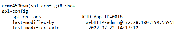
After you have performed the steps to configure the SPL plug-in to generate an Avaya UCID for every incoming call, you can verify the configuration.
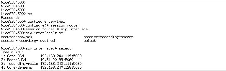
-
In the Acme Packet CLI, at the opening prompt, type:
configure terminal -
Press Enter.
The prompt changes to
YourSBC(configure)#. -
Type:
system -
Press Enter.
The prompt changes to
YourSBC(system)#. -
Type the following and press Enter:
spl-configThe prompt changes to
YourSBC(spl-config)#. -
Type the following and press Enter:
select -
Type the following and press Enter:
showThe configuration of the SPL plug-in for generating an Avaya UCID for every incoming call displays.
-
Type the following and press Enter:
exitThe prompt changes to
YourSBC(system)#. -
Type the following and press Enter:
exitThe prompt changes to
YourSBC(configure)#. -
Type the following and press Enter:
exitThe prompt changes to
YourSBC#.
(Optional) Encryption Prerequisites
-
Verifying one call leg is encrypted:
For encryption of the recorder call leg, verify that one of the other SBC call legs either going in/coming out of the SBC is encrypted.
-
Follow the Oracle documentation for configuring certificates.
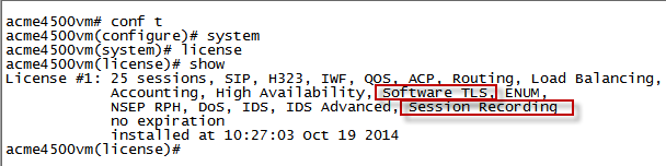
Verify the License
Verify that the license is valid and includes the Session Recording feature.
-
Connect to the Acme Packet CLI and type the user password.
-
Type the following and press Enter:
enable -
Type the superuser password and press Enter:
-
Type the following and press Enter:
configure terminal -
Type the following and press Enter:
system -
Type the following and press Enter:
license -
Type the following and press Enter:
show -
Verify that the license is valid (not expired).
-
Verify that the license includes Session Recording.
-
For SRTP, verify that the license includes Software TLS.
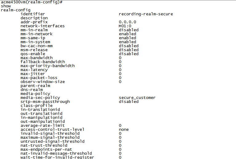
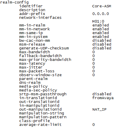
Configure the Recording Realm
-
Connect to the Acme Packet CLI and type the user password.
-
Type the following and press Enter:
enable -
Type the superuser and press Enter:
-
Type the following and press Enter:
configure terminal -
Type the following and press Enter:
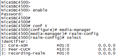
media-manager -
Type the following and press Enter:
realm-config -
Configure the realm name, type:
identifier <Name of the realm>This must be the same as the recording realm name you define in Configuring the Session Recording Server (SRS) Connection or (Optional) Configuring the Session Recording Group (SRG).
-
Configure the interface, type the following and press Enter:
network-interfaces <interface>For example:
network-interfaces M01:0 -
Configure the RTCP Mux feature, type the following and press Enter:
rtcp-mux enable -
Configure the Hide Egress Media Update feature, type the following and press Enter:
hide-egress-media-update enable -
Type the following and press Enter:
doneThe graphic above is for example purposes only. In a non secure environment, the media-sec- policy is blank.
Configure the Session Recording Server (SRS) Connection
The SRS is the VRSP.
-
Make sure you completed Configuring the Recording Realm.
-
Connect to the Acme Packet CLI and type the user password.
-
Type the following and press Enter:
enable -
Type the superuser password and press Enter.
-
Type the following and press Enter:
configure terminal -
Type the following and press Enter:
session-router -
Type the following and press Enter:
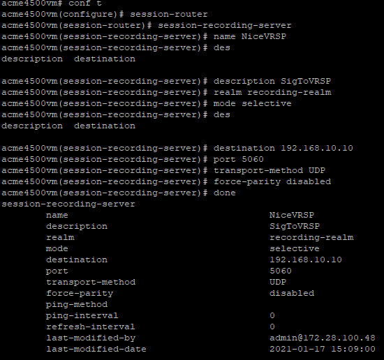
session-recording-server -
Configure the SRS name, type the following and press Enter:
name <name of the SRS>For example:
name NiceVRSP -
(Optional) Configure the SRS description, type the following and press Enter:
description <description of the SRS>For example:
description SignalingToVRSP -
Configure the SRS realm, type the following and press Enter:
realm <Name of the realm>For example:
realm recording-realm -
Configure the SRS mode, type the following and press Enter:
mode selective -
Configure the destination IP address, type the following and press Enter:
destination <IP address of the VRSP>For example:
destination 192.168.10.10 -
Configure the destination port:
-
In a non-secure environment, type
port 5060and press Enter -
In a secure environment, for a secure TLS connection, type
port 5061and press Enter -
In a secure environment, for a mutual TLS connection, type
port 5065and press Enter
-
-
Configure the transport layer protocol:
-
In a non-secure environment, for TCP as the transport layer protocol, type
transport-method TCPand press Enter -
In a secure environment, type
DynamicTLSand press Enter
-
-
Type the following and press Enter:
done -
Add the SRS to a SIP Interface, Realm, or Agent Session. See Configuring SIP Interfaces, Realms, and Session Agents for the SRS and SRG.
While you can add the SRS to all three recording options, the system automatically prioritizes your selection in this order: first Agent Session, then Realm, and then SIP Interface.
-
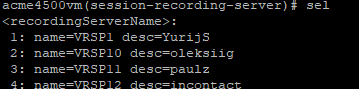
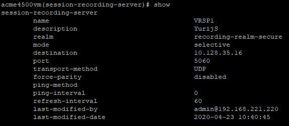
To enable recording with recorders that expect RTP on consecutive ports (VoIP loggers), you must disable force-parity. By default, force-parity is already disabled using the force-parity parameter. To verify that force-parity is disabled, type:
configure terminalsession-routersession-recording-serverselect [choose the recording server name by number]showThe configuration of the Session Recording Server appears.
-
Check that force-parity is disabled.
-
If force-parity is enabled, type the following and press Enter:
force-parity disableddone -
Save and activate the configuration.
(Optional) Configure the Session Recording Group (SRG)
Configure this if you have more than one recorder.
-
Verify you completed Configuring the Recording Realm.
-
Connect to the Acme Packet CLI and type the user password.
-
Type the following and press Enter:
enable -
Type the superuser password and press Enter.
-
Type the following and press Enter:
configure terminal -
Type the following and press Enter:
session-router -
Type the following and press Enter:
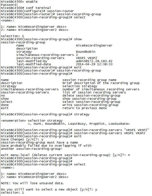
session-recording-group -
Configure the SRG name, type the following and press Enter:
name SRG:<name of the session recording group>For example:
name SRG:NiceRecordingServer -
(Optional) Add the SRG description, type the following and press Enter:
description <description of the SRG>For example:
description SignalingToRecGroup -
Configure the strategy of the SRG, for example, RoundRobin (see below). Type the strategy name and press Enter:
strategy RoundRobinNote that a NiCE VRSP pair does not support load balancing.
-
To view additional strategy options (such as Hunt, LeastBusy, PropDist, and LowSusRate), type the following and press Enter:
strategy? -
Configure the number of session recording servers that will be allocated to the SRG, type the following and press Enter:
simultaneous-recording-serversfollowed by the number of servers.
For a NiCE VRSP pair, the number is 2.
-
Type
exitand repeat this action until you reach the first superuser prompt (#), for example:NiceSBC4500(configure)# session-router
NiceSBC4500(session-router)# session-recording-group
NiceSBC4500(session-recording-group)# exit
NiceSBC4500(session-router)# exit
NiceSBC4500(configure)# exit
NiceSBC4500#
-
Specify the session recording servers to be included in the group. Type the session recording server names in quotation marks, with a space between each session recording server name, and press Enter:
"<servername1> <servername2>"This must be the same as the recording realm name you define in Configuring the Session Recording Server (SRS) Connection.
-
Type the following and press Enter:
done -
Type the following and press Enter:
verify-config -
When you receive the notice Verification successful, type the following and press Enter:
save-config -
Type the following and press Enter:
activate-config
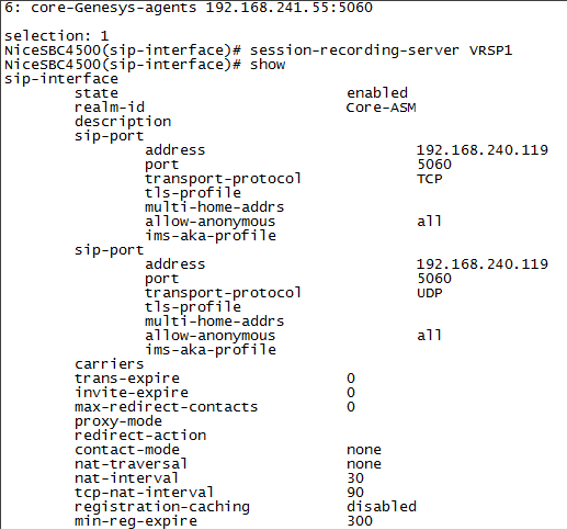
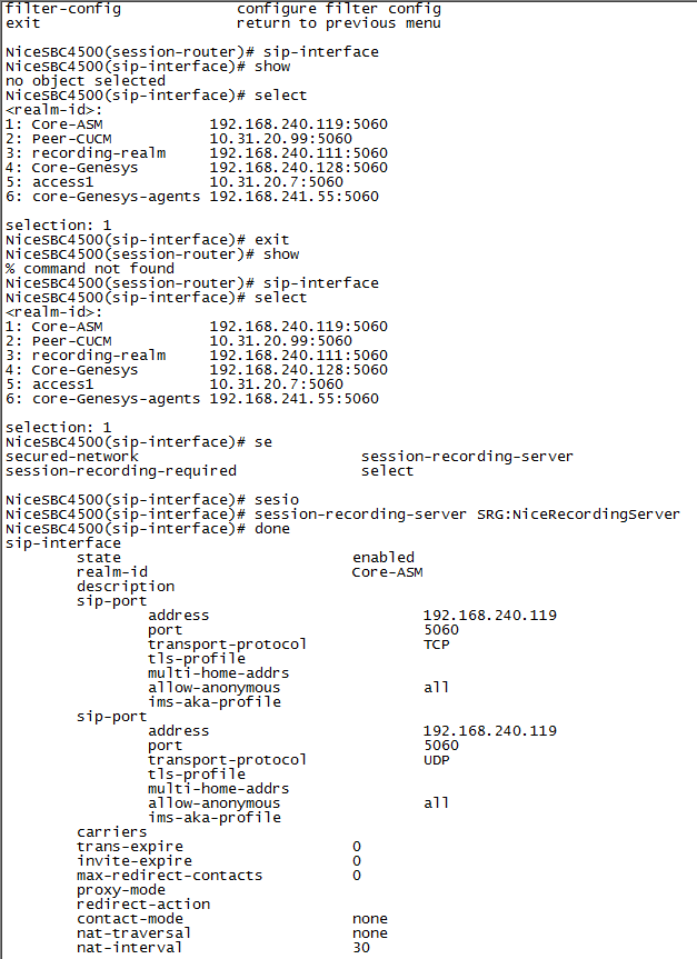
Configure SIP Interfaces, Realms, and Session Agents for the SRS and SRG
While you can select all of these interfaces for the components above, the system will automatically prioritize the selection in this order: first session agent, then realm, and then SIP interface.
-
Verify you completed Configure the Recording Realm.
-
Connect to the Acme Packet CLI and type the user password.
-
Type the following and press Enter:
enable -
Type the superuser password and press Enter:
-
Type the following and press Enter:
configure terminal -
Type the following and press Enter:
session-router -
Type the following and press Enter:
sip-interface -
Type the following and press Enter:
select -
Select the SIP interface and type the number for that interface.
For example, if you want to record the Core-ASM SIP interface, as in the example above, type 1.
-
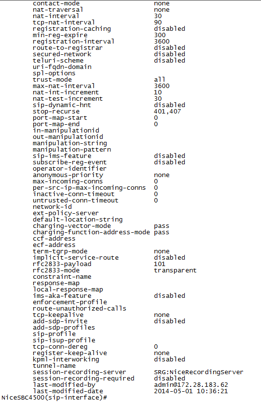
Define the SRS that will record the selected SIP interface, type the following and press Enter:
session-recording-server <name of the SRS>This must be the same SRS name you defined in Configuring the Session Recording Server (SRS) Connection.
For example:
name NiceVRSP -
Type the following and press Enter:
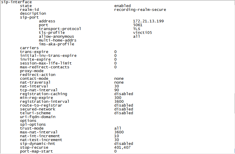
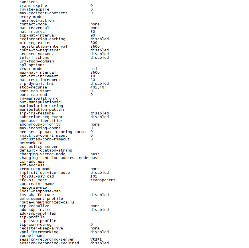
doneNon-secure example:
Secure example:
-
Scroll down to view the session recording server field.
-
Type
exitseveral times until you reach the superuser prompt (#) level. -
Type the following and press Enter:
verify-config -
When you receive the notice Verification successful, type the following and press Enter:
save-config -
Type the following and press Enter:
activate-config
-
Connect to the Acme Packet CLI and type the user password.
-
Type the following and press Enter:
enable -
Type the superuser password and press Enter:
-
Type the following and press Enter:
configure terminal -
Type the following and press Enter:
session-router -
Go to the SIP interface, type the following and press Enter:
sip-interface -
Type the following and press Enter:
selectIn this example, the recording is not encrypted.
-
Select the SIP interface and type the number for that interface.
For example, if you want to record the Core-ASM SIP interface, as in the example above, type 1.
-
Define the SRG that will record the selected SIP interface, type the following and press Enter:
session-recording-group SRG:<name of the session recording group>This must be the same SRG name you defined in (Optional) Configuring the Session Recording Group (SRG).
For example:
name SRG:NiceRecordingServer. Remember to includeSRG:before the name of the session recording group. -
Type the following and press Enter:
done -
Type
exitseveral times until you reach the superuser prompt (#) level. -
Type the following and press Enter:
verify-config -
When you receive the notice Verification successful, type the following and press Enter:
save-config -
Type the following and press Enter:
activate-config
-
Connect to the Acme Packet CLI and type the user password.
-
Type the following and press Enter:
enable -
Type the superuser password and press Enter:
-
Type the following and press Enter:
configure terminal -
Type the following and press Enter:
media-manager -
Go to the SIP interface, type the following and press Enter:
realm-config -
Type the following and press Enter:
selectThe list of available realms displays with a number next to each realm.
-
In the row marked
selection, type the number of the ingress or egress realm that you want to configure.For example, if you want to display the Core-ASM realm, type 1.
-
In the
(realm-config)#row, type the following and press Enter:showThis displays the details of the selected realm.
-
If you are configuring the SRS, in the
(realm-config)# session-recording-serverrow, enter the name of the session recording server. -
If you are configuring the SRG, in the
(realm-config)# session-recording-grouprow, enter the name of the session recording group.For example:
name SRG:NiceRecordingServer. Remember to includeSRG:before the name of the session recording group. -
Type the following and press Enter:
done -
Type
exitseveral times until you reach the superuser prompt (#) level. -
Type the following and press Enter:
verify-config -
When you receive the notice Verification successful, type the following and press Enter:
save-config -
Type the following and press Enter:
activate-config
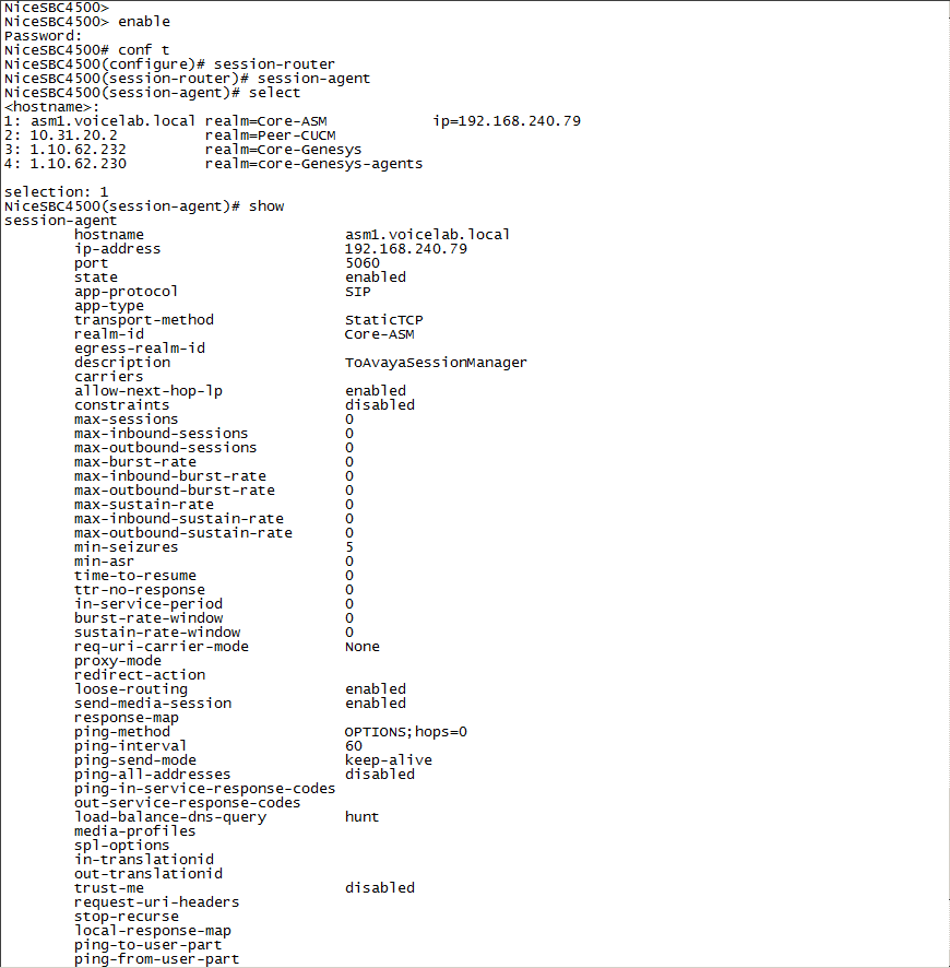
-
Connect to the Acme Packet CLI and type the user password.
-
Type the following and press Enter:
enable -
Type the enable password and press Enter:
-
Type the following and press Enter:
configure terminal -
Type the following and press Enter:
session-router -
Type the following and press Enter:
session-agent -
Type the following and press Enter:
selectA list of configured session agents appears.
-
Type the number of the agent that you want to record.
For example, if you want to record the Session Agent, type 1.
-
Define the session recording server that will record the selected session agent. Type the following and press Enter:
session-recording-server <name of the session recording server>This must be the same SRS name you defined in Configure the Session Recording Server (SRS) Connection.
For example:
name NiceVRSP. -
Type the following and press Enter:
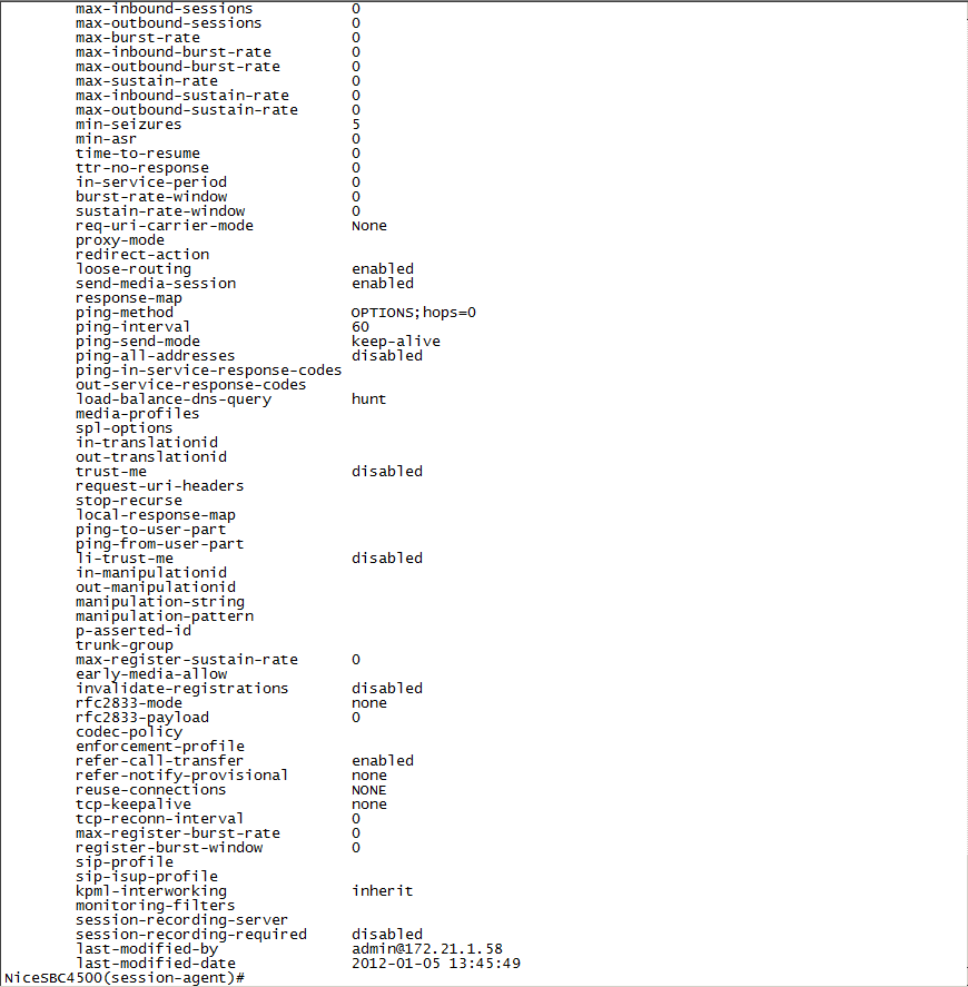
doneThe configured information for the session agent to be recorded appears.
-
Scroll down to view the session-recording-server field.
-
Type
exitseveral times until you reach the enable prompt (#) level. -
Type the following and press Enter:
verify-config -
When you receive the notice Verification successful, type the following and press Enter:
save-config -
Type the following and press Enter:
activate-config

-
Connect to the Acme Packet CLI and type the user password.
-
Type the following and press Enter:
enable -
Type the enable password and press Enter:
-
Type the following and press Enter:
configure terminal -
Type the following and press Enter:
session-router -
Type the following and press Enter:
session-agent -
Type the following and press Enter:
selectA list of configured session agents appears.
-
Type the number of the agent that you want to record.
For example, if you want to record the Core-ASM session agent, type 1.
-
Define the session recording group (SRG) that will record the selected session agent. Type the following and press Enter:
session-recording-group SRG:<name of the session recording group>This must be the same SRG name you defined in (Optional) Configure the Session Recording Group (SRG).
For example:
name NiceVRSP. -
Type the following and press Enter:
doneThe configured information for the session agent to be recorded appears.
-
Scroll down to view the session-recording-server field.
-
Type
exitseveral times until you reach the enable prompt (#) level. -
Type the following and press Enter:
verify-config -
When you receive the notice Verification successful, type the following and press Enter:
save-config -
Type the following and press Enter:
activate-config
Prepare AudioCodes SBC
This section describes how to prepare and configure the AudioCodes Session Border Controller (SBC) to integrate with Real-Time Third Party Telephony Recording (Multi-ACD).
The supported AudioCodes SBC version is 7.4.
The procedures described in this section are recommendations only. The AudioCodes site engineer must perform the AudioCodes preparation and configuration.
The SBC must have a valid TLS certificate installed. The certificate must be signed by a trusted Certificate Authority (CA) listed in the Supported Certificate Authorities for SIPREC section.
Workflow
Use this workflow to prepare your AudioCodes SBC system for Real-Time Third Party Telephony Recording (Multi-ACD).
Step 1: Verify the License
Step 2: Configure the Proxy Set for NiCE CXone Environment
Step 3: Configure the IP Group for the NiCE CXone AudioCodes SBC
Step 4: (Secure/Non-secure Environments) Configure SIP Recording
Step 5: Send a UCID to the NiCE CXone AudioCodes SBC
Workflow for Secure SIPREC
Use this workflow to prepare your AudioCodes SBC system for secure SIPREC configuration with Real-Time Third Party Telephony Recording (Multi-ACD).
Step 1: Verify the License
Step 2: (Secure Environments only) Configure the Proxy Set
Step 3: Configure Secure IP Profile
Step 4: (Secure Environments only) Configure the IP Group
Step 5: (Secure Environments only) Import and Export Certificates for SIP Recording
Step 6: (Secure/Non-secure Environments) Configure SIP Recording
Step 7: Send a UCID to the NiCE CXone AudioCodes SBC
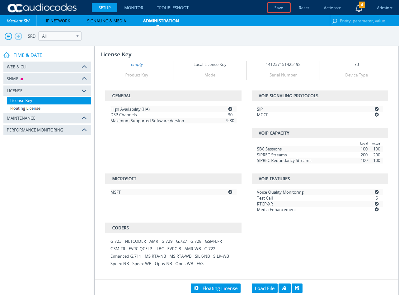
Verify the License
Verify that the license is valid and that the SBC-SIPREC feature is supported.
-
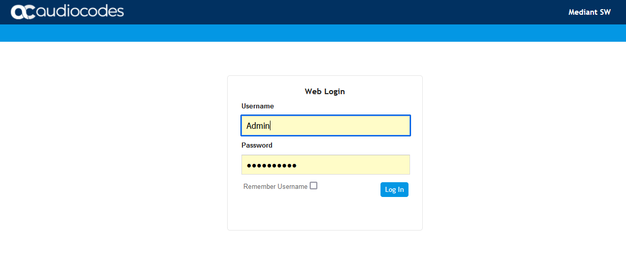
Connect to the AudioCodes SBC via web.
-
Click the ADMINISTRATION menu.
-
Under TIME & DATE, expand MAINTENANCE and select License Key.
-
Under VOIP FEATURES, verify that the license supports SIPRec Sessions.
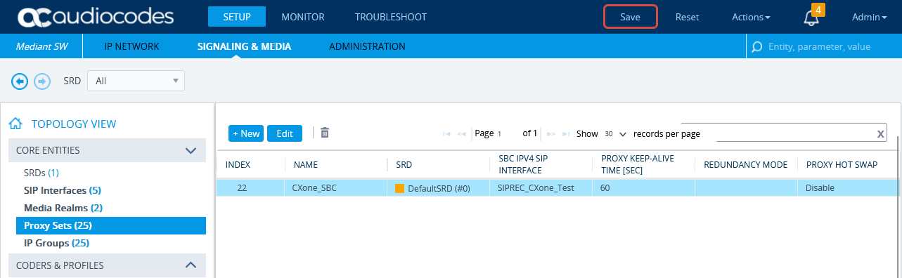
Configure the Proxy Set for NiCE CXone Environment
This procedure provides guidelines for configuring the SBC for the NiCE CXone AudioCodes SBC, including the IP address of the NiCE CXone AudioCodes SBC.
-
In the menu, click SIGNALING & MEDIA.
-
Under TOPOLOGY VIEW, expand CORE ENTITIES and select Proxy Sets.
-
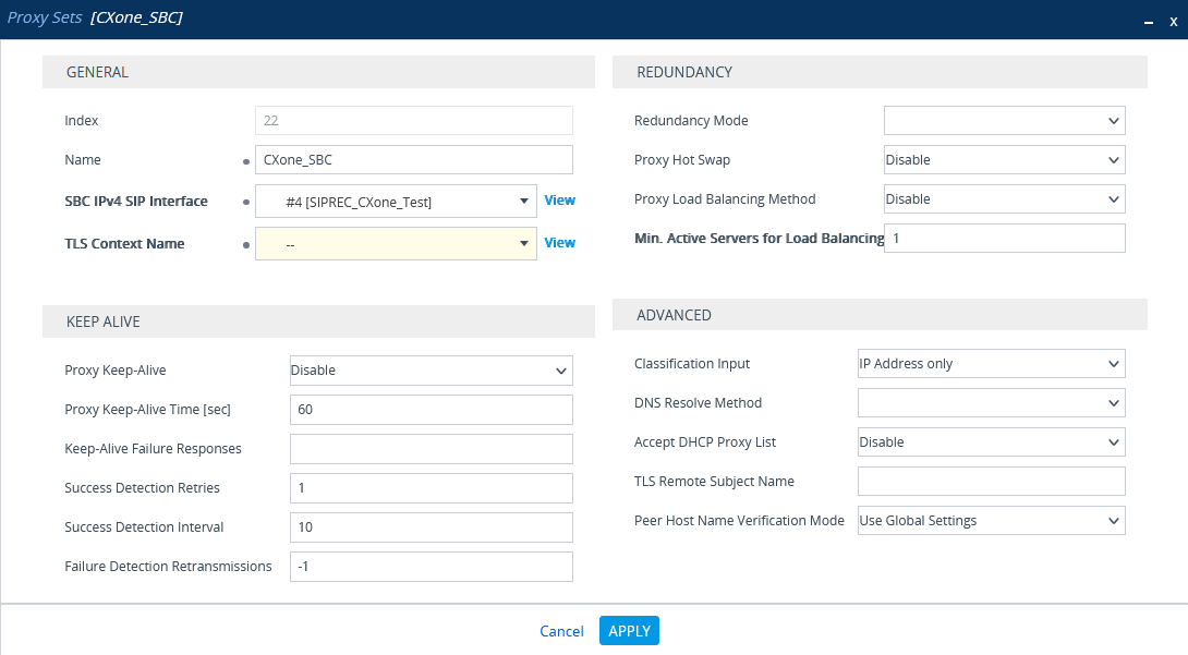
In the list of Proxy Sets, click New.
-
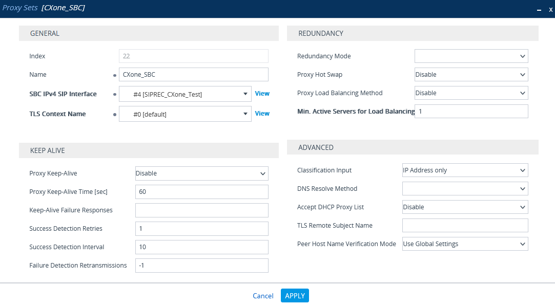
In the Proxy Set window, under GENERAL:
-
In the Name field, enter a name.
-
From the SBC IPv4 SIP Interface drop-down list, select the SIP interface.
-
Click APPLY.
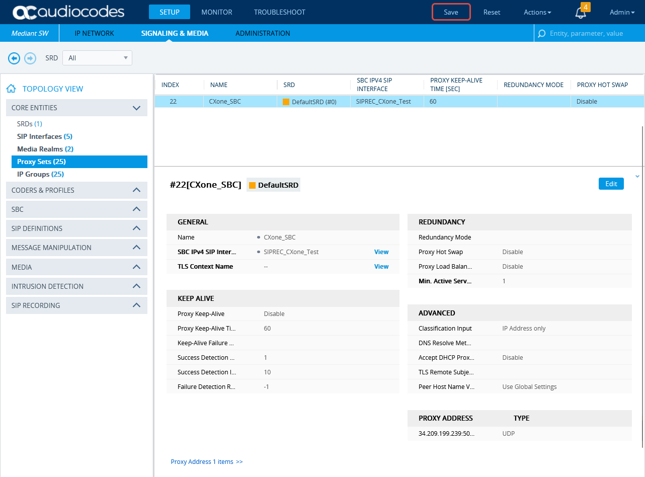
-
-
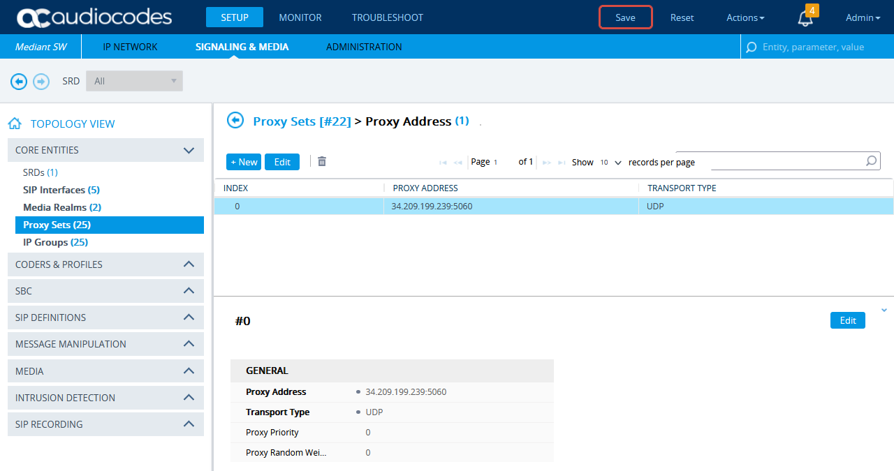
Scroll down and click the Proxy Address link.
-
In the Proxy Sets > Proxy Address window, click New and add IP address for NiCE CXone AudioCodes SBC.
-
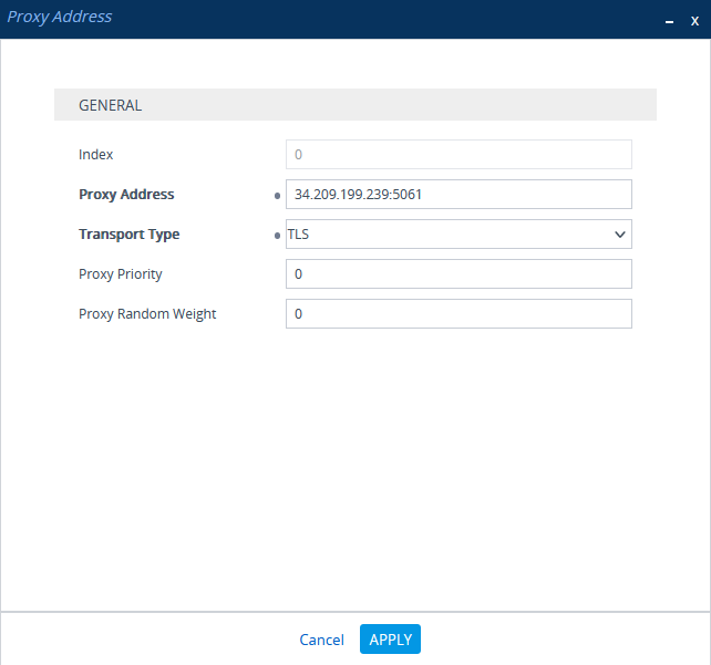
In the Proxy Address window, under GENERAL, in the Proxy Address field, enter the NiCE CXone AudioCodes SBC IP address.
-
Click APPLY.

(Secure Environments only) Configure the Proxy Set
This procedure provides guidelines for configuring the SBC Proxy Set and the Proxy IP address for the NiCE CXone AudioCodes SBC for secure connection.
-
In the menu, click SIGNALING & MEDIA.
-
Under TOPOLOGY VIEW, expand CORE ENTITIES and select Proxy Sets.
-
In the list of Proxy Sets, click New.
-
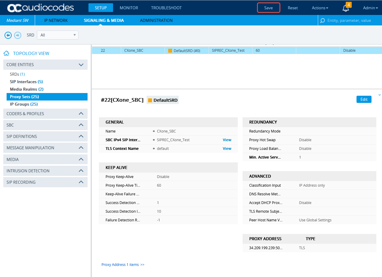
In the Proxy Set window, under GENERAL:
-
In the Name field, enter a name.
-
From the SBC IPv4 SIP Interface drop-down list, select the SIP interface.
-
From the TLS Context Name drop-down list, select the TLS Context with the SBC certificate.
-
-
Scroll down and click the Proxy Address link.
-
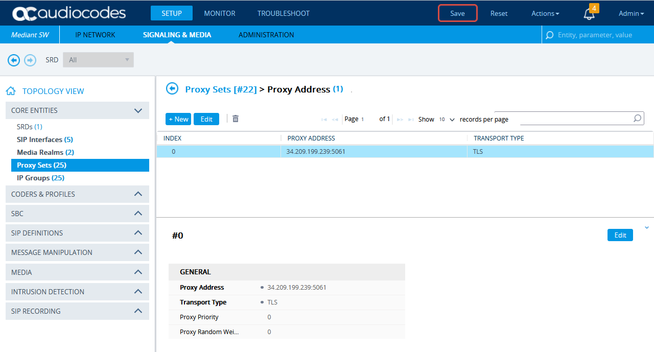
In the Proxy Sets > Proxy Address window, click New and add the IP address for NiCE CXone AudioCodes SBC.
-
In the Proxy Address window, under GENERAL, in the Proxy Address field, enter the NiCE CXone AudioCodes SBC IP address and set the Transport Type to TLS.
-
Click APPLY.
Configure Secure IP Profile
-
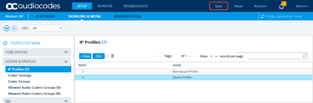
From the Setup menu, go to SIGNALING & MEDIA. Under TOPOLOGY VIEW, expand CODERS & PROFILES and select IP Profiles.
-
In the list of IP Profiles, click New.
-
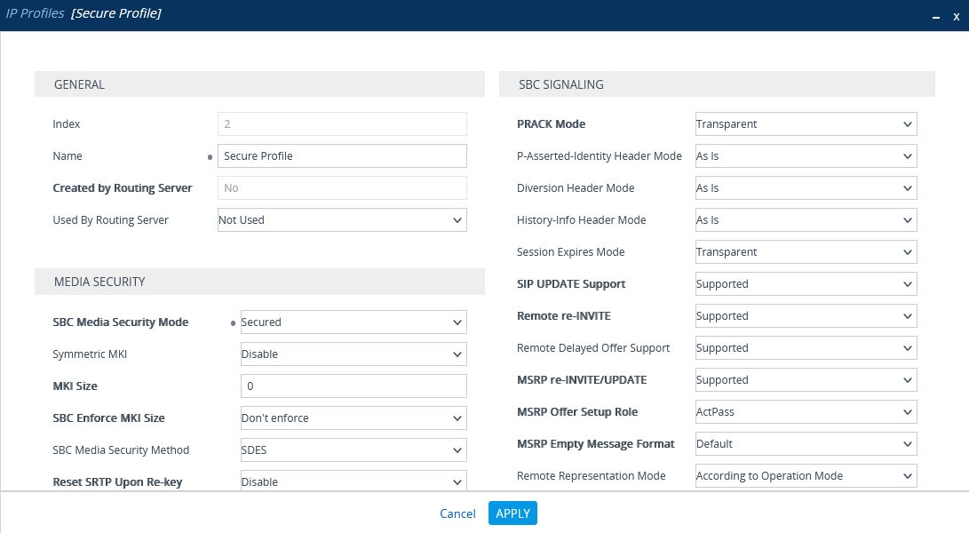
In the list IP Profiles window, under MEDIA SECURITY, make sure the SBC Media Security Mode is set to Secured.
-
Click APPLY.
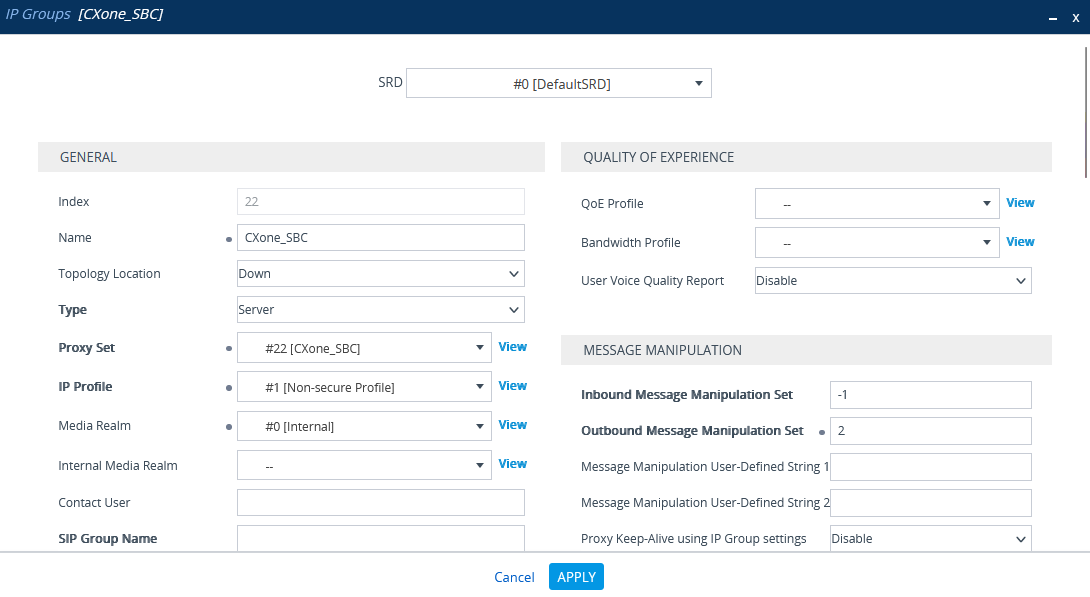
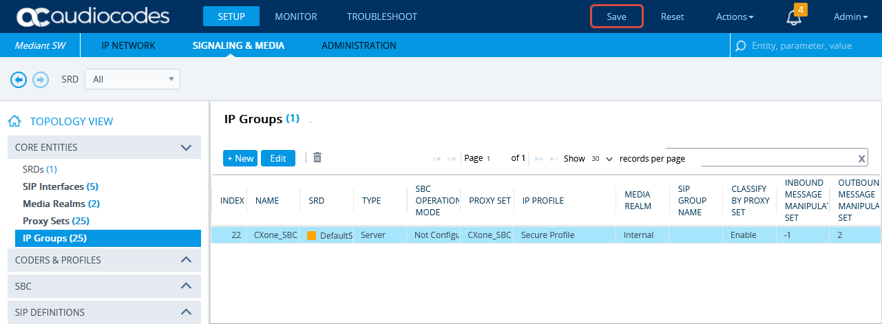
Configure the IP Group for the NiCE CXone AudioCodes SBC
-
In the menu, click SIGNALING & MEDIA.
-
Under TOPOLOGY VIEW, expand CORE ENTITIES and select IP Groups.
-
In the list of IP Groups, click New.
-
In the IP Groups window, under GENERAL:
-
In the Index field, configure the next sequential number.
-
In the Name field, enter a name.
-
From the Topology Location drop-down list, select the location.
-
From the Type drop-down list, select Server.
-
From the Proxy Set field, select the Proxy Set for this IP Group.
-
In the IP Profile field, enter an existing IP Profile ID.
-
In the Media Realm Name field, select the existing Media Realm name.
-
-
Click APPLY.
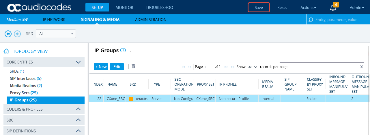
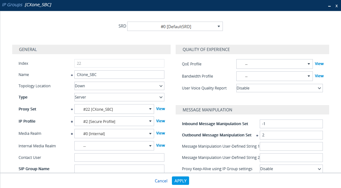
(Secure Environments only) Configure the IP Group
Verify that the secure IP Profile was configured. See Configure Secure IP Profile.
-
In the menu, click SIGNALING & MEDIA.
-
Under TOPOLOGY VIEW, expand CORE ENTITIES and select IP Groups.
-
In the list of IP Groups, click New.
-
In the IP Groups window, under GENERAL:
-
In the Index field, configure the next sequential number.
-
In the Name field, enter a name.
-
From the Topology Location drop-down list, select the location.
-
From the Type drop-down list, select Server.
-
From the Proxy Set field, select the NiCE CXone Proxy Set for this IP Group.
-
In the IP Profile field, select the secure IP Profile previously created in Configure Secure IP Profile.
-
In the Media Realm Name field, select the existing Media Realm name.
-
-
Click APPLY.
-
Then click Save.
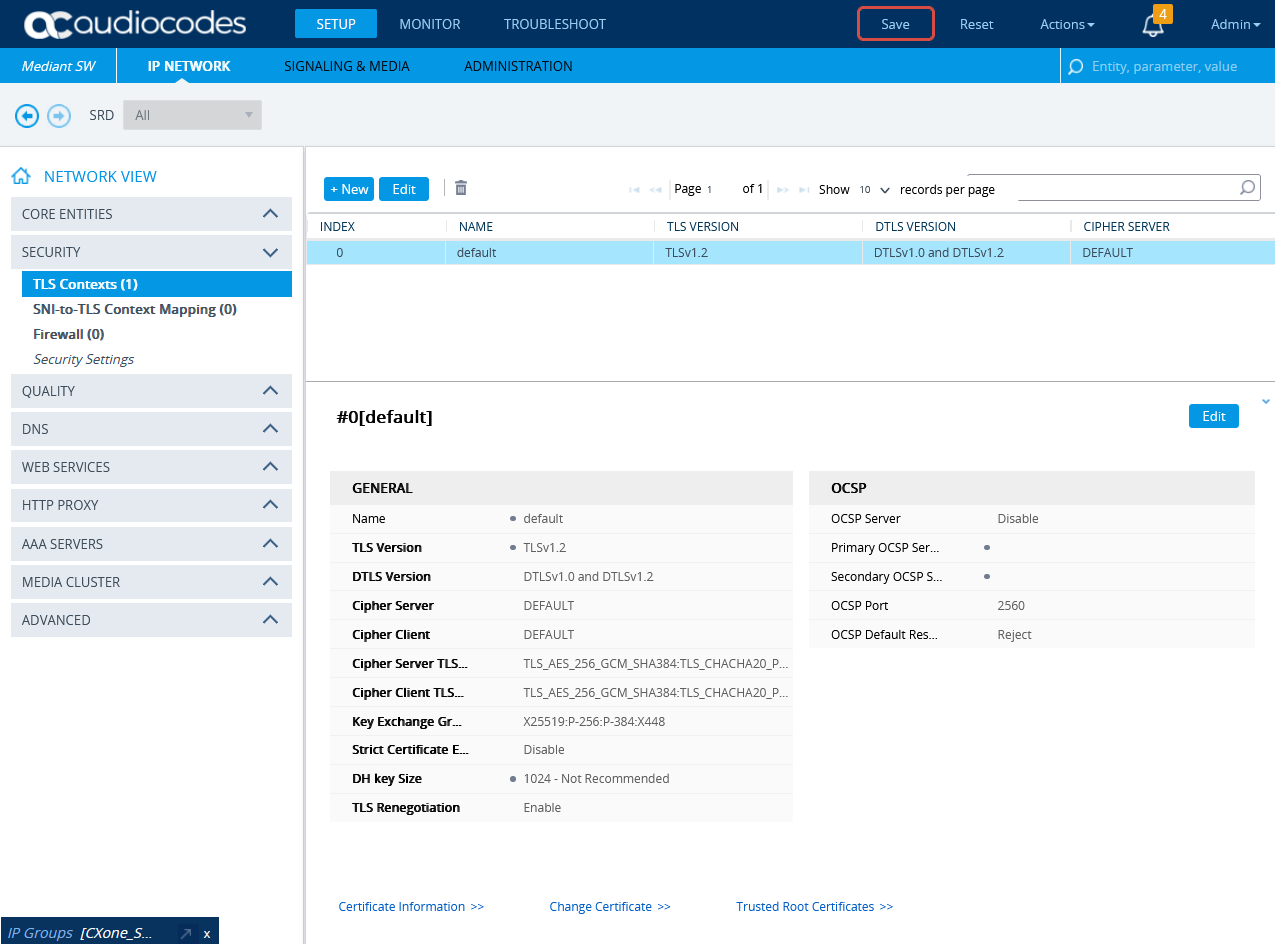
(Secure Environments only) Import and Export Certificates for SIP Recording
At the end of this step, you are required to provide to NiCE Professional Services:
-
The certificate in PEM format
Before import, the NiCE CXone AudioCodes SBC certificate must be saved in PEM format.
-
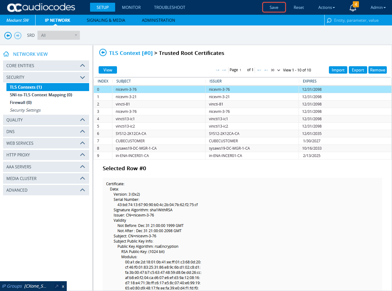
To import the NiCE CXone AudioCodes SBC certificate to the SBC, go to SETUP > IP NETWORK. Under NETWORK VIEW, expand SECURITY and select TLS Contexts.
-
In the TLS Context window, click Trusted Root Certificates.
-
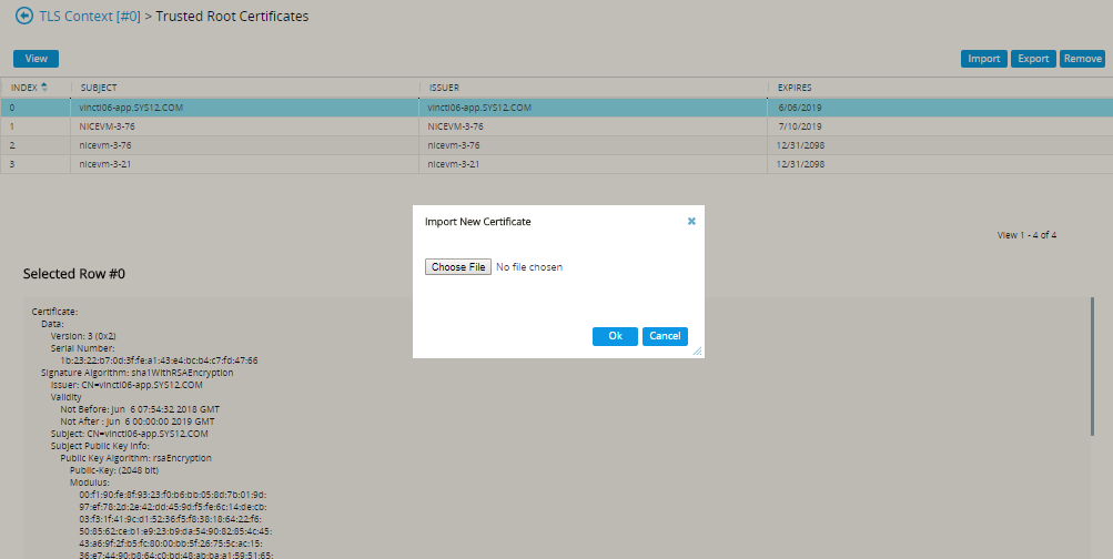
Click Import.
-
In the Import New Certificate window, click Choose File and browse to the NiCE CXone AudioCodes SBC certificate. Verify the NiCE CXone AudioCodes SBC certificate is in PEM format.
-
Click OK.
-
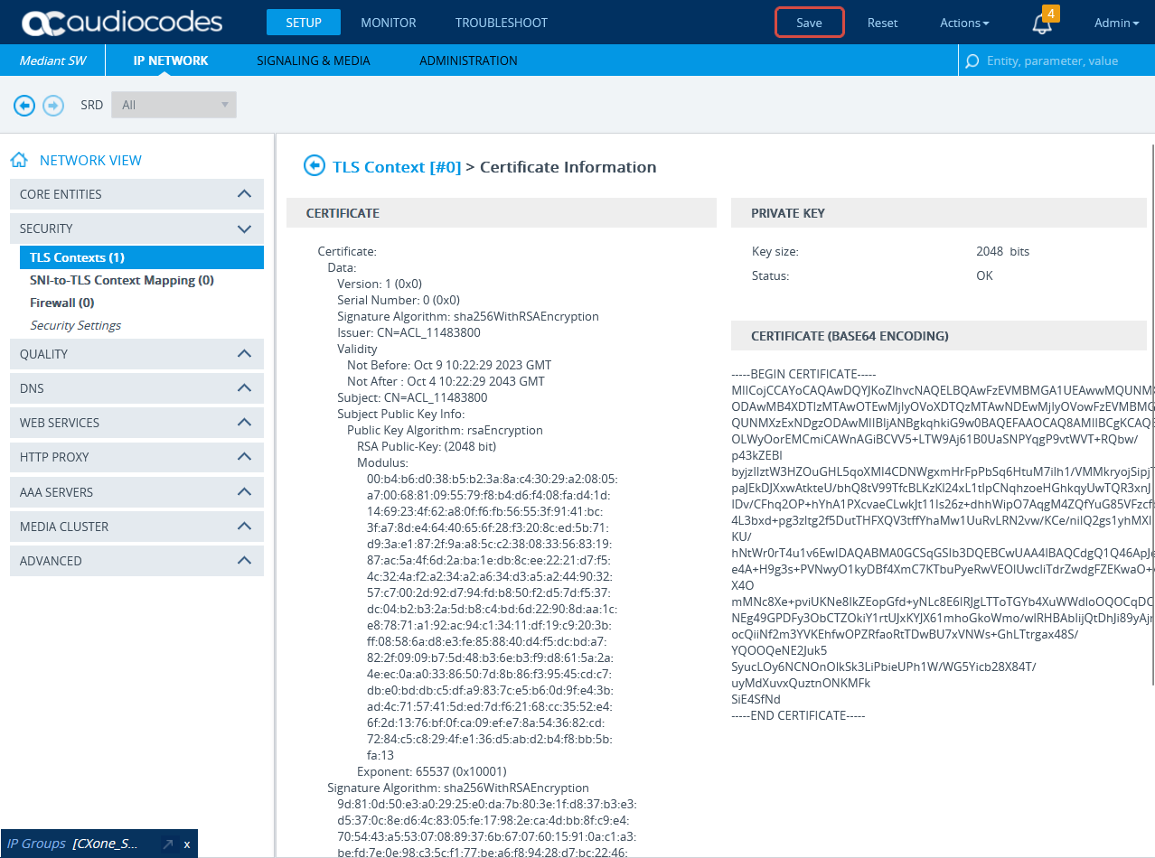
In the TLS Contexts window, click Certificate Information.
-
On the Certificate Information page, under CERTIFICATE, copy the text of the certificate. Create a certificate from this text.
-
Send the certificate in PEM format to the NiCE Professional Services together with the CA, if exists.
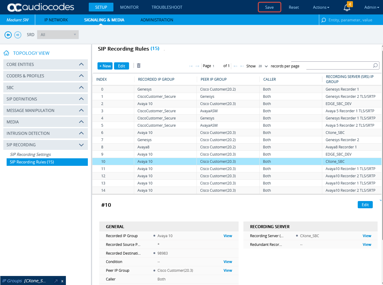
(Secure/Non-secure Environments) Configure SIP Recording
This section describes the procedure for SIP Recording enablement and the SIP Recording routing configuration.
-
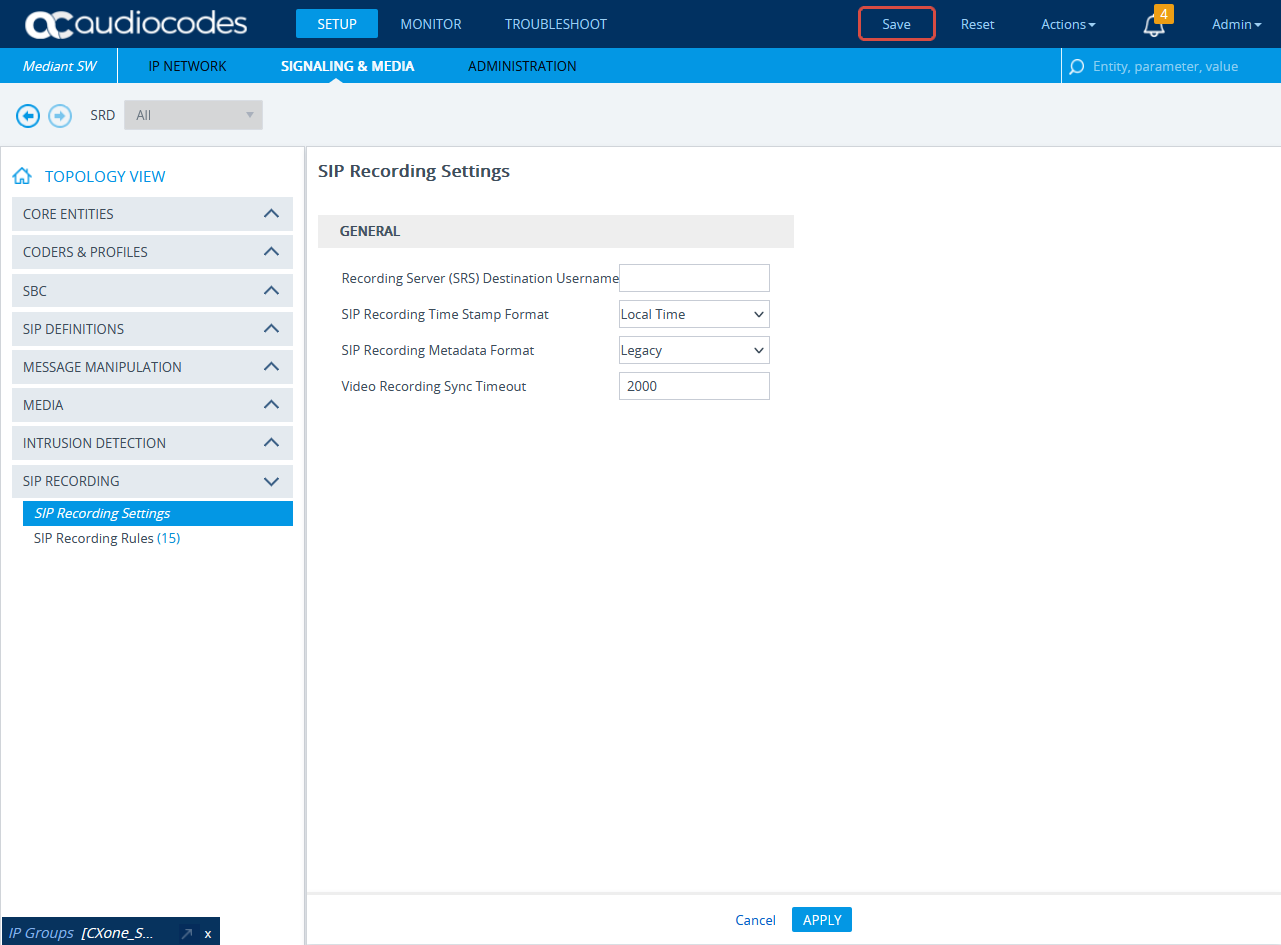
In the menu, click SIGNALING & MEDIA.
-
Expand SIP RECORDING and select SIP Recording Settings.
-
Under General, from the SIP Recording Metadata Format drop-down list, select either Legacy or RFC 7865 Metadata option. Real-Time Third Party Telephony Recording (Multi-ACD) supports both options. Configure according to your preferences.
-
Click APPLY.
-
Form SIP RECORDING, select SIP Recording Rules.
-
In the SIP Recording Rules area, click New.
-
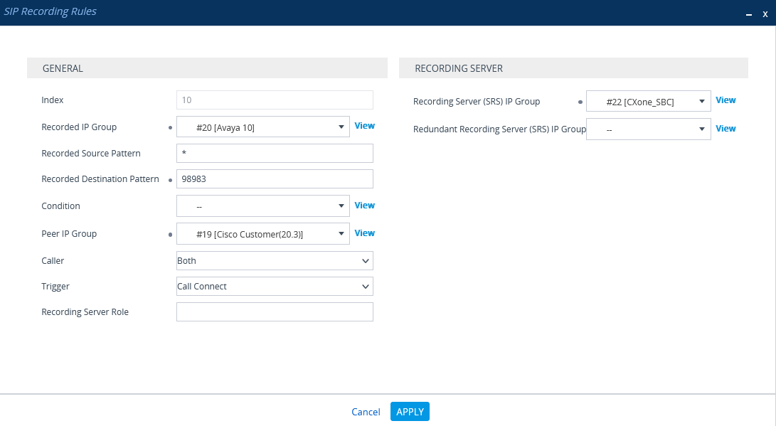
In the SIP Recording Rules window, under GENERAL:
-
From the Recorded IP Group list, select the existing agent's side group ID.
-
In the Recorded Source Pattern field, enter the source prefix to be recorded.
-
In the Recorded Destination Pattern field, enter the destination prefix to be recorded.
-
From the Peer IP Group list, select the Service Provider side's group ID.
-
From the Caller list, select Both.
-
-
Under RECORDING SERVER:
-
From the Recording Server (SRS) IP Group list, select the previously created IP Group for the Recorder.
See Configure the IP Group for the NiCE CXone AudioCodes SBC or (Secure Environments only) Configure the IP Group.
-
-
Click APPLY.
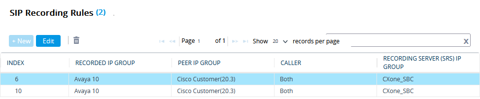
-
A new row is added in the SIP Recording Routing section.
-
To save all new information, click Save.
Send a UCID to the NiCE CXone AudioCodes SBC
In an Avaya environment, the Universal Call Identifier (UCID) of every call must be sent to the NiCE CXone AudioCodes SBC.
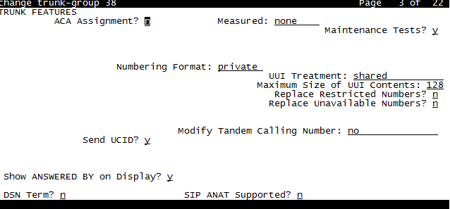
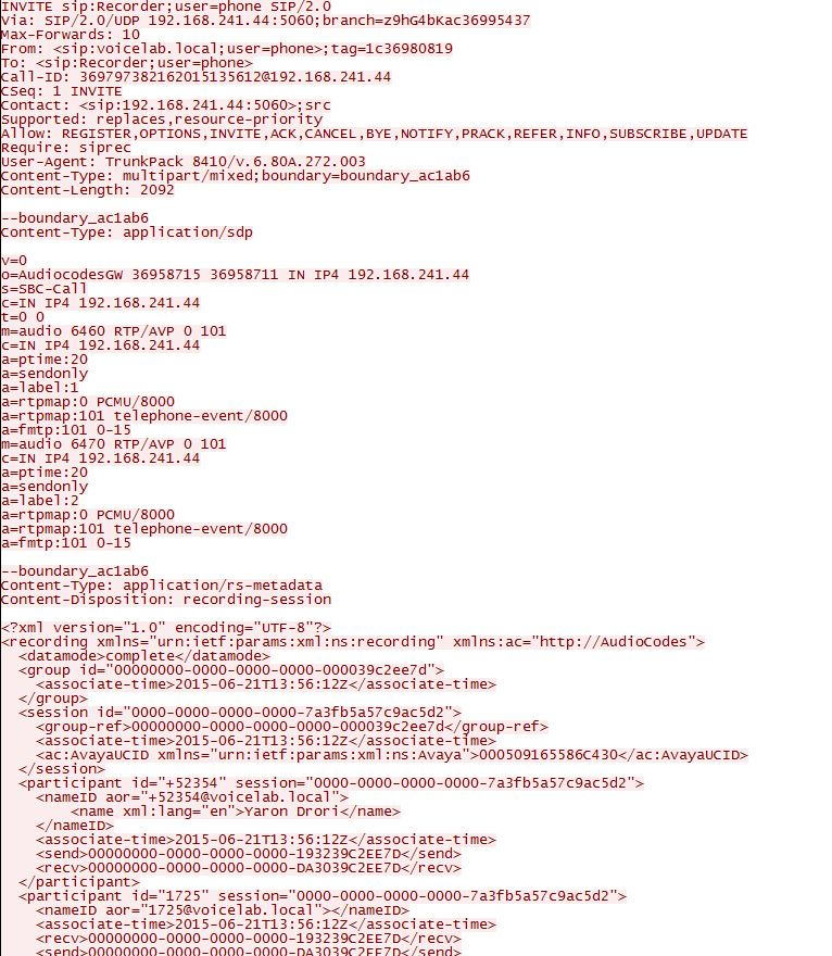
For egress calls, Avaya CM generates the UCID and then converts it to the User to User Information (UUI), which is sent from the Avaya Session Manager to the AudioCodes SBC in the User-to-User field of the SIP INVITE header, see image below.
In a trace the UUI appears as a hexadecimal value, and in an Avaya CTI event it is displayed as a decimal number (the UCID). The UUI (which contains the UCID) is sent to the AudioCodes SBC, which subsequently sends the UCID to the NiCE CXone AudioCodes SBC.
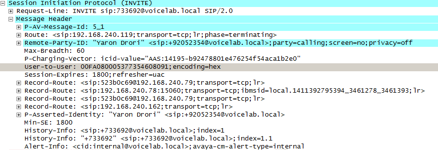
On the Avaya CM, the UUI treatment must be configured as Shared on the trunk to the Avaya Session Manager.
The UCID may or may not be included in an ingress call, that is, a call directed from the service provider to an agent, when it arrives at the AudioCodes SBC. If the UCID is not included, the SBC must generate it.
If the UCID is already included in an ingress call, the SBC should not generate a different UCID.
Follow these steps to enable the SBC generation of the Avaya UCID in the SBC.
-
In the menu, click SIGNALING & MEDIA.
-
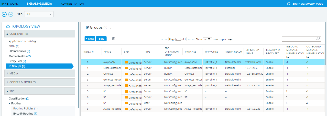
Under TOPOLOGY VIEW, expand CORE ENTITIES and select IP Groups.
-
In the IP Groups table, select the IP Group for Avaya and click Edit.
-
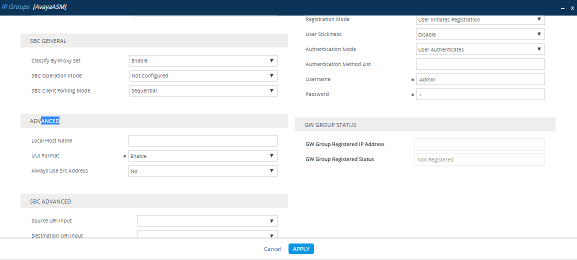
In the IP Groups window, scroll down to ADVANCED.
-
From the UUI Format drop-down list, select Enable.
-
Click Apply.
-
Click Save and then click Yes.
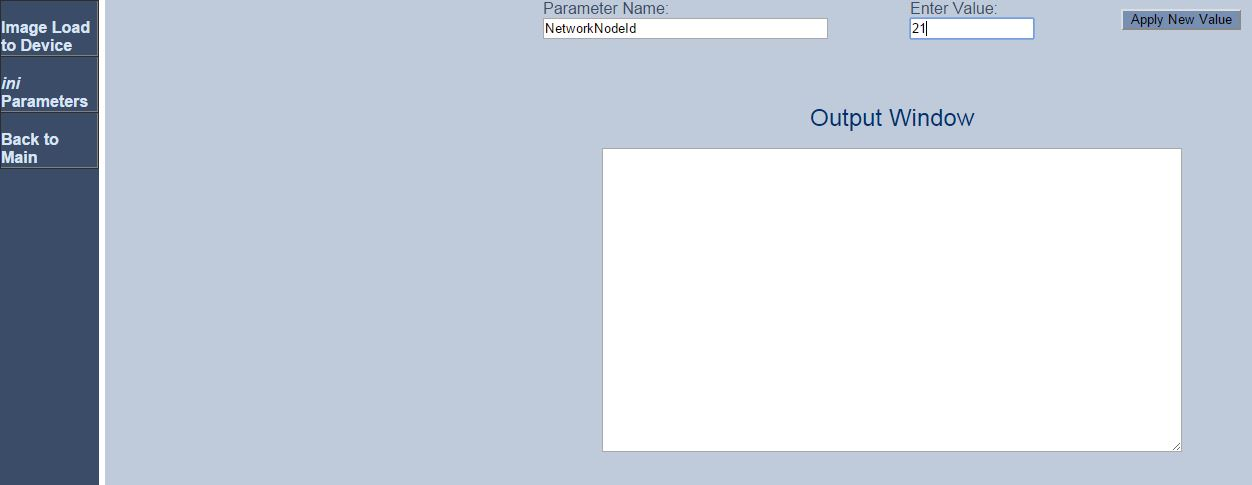
The UCID includes an identifier of the node that created it. Configure the value of the node ID that will be used in each UCID generated by the AudioCodes SBC.
-
Use the browser to access the AudioCodes SBC Admin Page. Input this URL:
Http://AudioCodes IP Address/AdminPage -
Log in using your username and password.
-
Click ini Parameters.
-
In the Parameter Name field, type NetworkNodeId.
-
In the Enter Value field, enter a unique node ID. This node ID must be a unique ID that is not used by any Avaya CM in the local network.
-
Click Apply New Value.
Once a call is established through the AudioCodes SBC, the SBC sends a SIP INVITE message to the NiCE CXone AudioCodes SBC. After confirmation by the NiCE CXone AudioCodes SBC, the SBC forks the audio and sends it to the NiCE CXone AudioCodes SBC.
The NiCE CXone AudioCodes SBC is expected to receive the UCID in the SIP INVITE message sent from the SBC during an ingress call or an egress call. The following is an example of the metadata part of a SIP INVITE message sent from the SBC to the NiCE CXone AudioCodes SBC, the <ac:AvayaUCID xmlns="urn:ietfarams:xml:ns:Avaya">0015EE805586C304</ac:AvayaUCID> element contains the UCID.
For example, the UCID value here is highlighted:
<ac:AvayaUCID xmlns="urn:ietfarams:xml:ns:Avaya">0015EE805586C304</ac:AvayaUCID>
Prepare Avaya SBC for Enterprise (SBCE) Environment
This section describes how to prepare the Avaya environment for integrating the Avaya Session Border Controller for Enterprise (SBCE) with Real-Time Third Party Telephony Recording (Multi-ACD) environment for SIPREC communication.
The supported Avaya SBCE versions are 8.1.3, 10.1 and 10.2..
The procedures described in this guide are recommendations only and should be performed by a certified Avaya site engineer.
For comprehensive information about configuring the Avaya switch, see the Avaya documentation.
When you perform these procedures, do not select the Avaya default value (*) in steps where a specific value (for example, a specific transport protocol) is indicated.
Workflow
Use this workflow to set up Avaya SBCE active recording with Real-Time Third Party Telephony Recording (Multi-ACD).
The SBC must have a valid TLS certificate installed. The certificate must be signed by a trusted Certificate Authority (CA) listed in the Supported Certificate Authorities for SIPREC section.
Before beginning this workflow, you must ensure that site components are configured.
-
Step 1: Configure the TLS
-
Step 2: Configure a Recording Server
-
Step 3: Create a Routing Profile
-
Step 5: Create a Recording Profile
-
Step 6: Create a Session Policy
-
Step 7: Create an Application Rule
-
Step 8: Create a Media Rule
-
Step 9: Create an Endpoint Policy Group
-
Step 10: Add a Session Flow
-
Step 11: Create a Server Flow
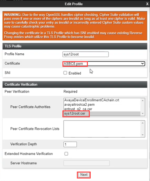
Configure the TLS
Before you begin, make sure the TLS Port and TLS Client profile is configured correctly for internal signaling leg under Network & Flows > Signaling Interface.
-
Select TLS Management from the menu.
-
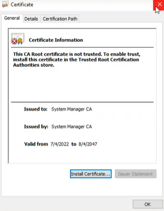
Click Certificates, under Installed Certificates view the certificate, for example ASBC8.pem.
This is not a self signed certificate.
-
To obtain the certificate, send the NiCE Professional Services representative the CA certificate that is signed for this SBC.
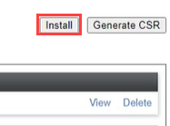
-
Once you have obtained the NiCE Certificate, click Install.
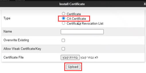
-
Select CA Certificate, provide a name for the certificate.
-
Click Browse, navigate to the certificate on your system.
-
Click Upload.
The ASBC certificate is displayed under Installed Certificates.
-
Click Client Profiles.
-
Click Add.
-
Provide a Profile Name.
-
Allocate the SBC certificate to Certificate and the NiCE certificate to Peer Certificate Authorities.
-
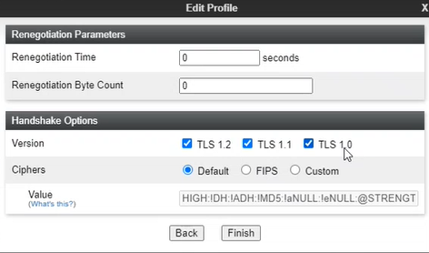
Click Next.
-
Obtain the TLS Version from the NiCE Professional Services representative.
-
Click Finish. The client profile is displayed under Client Profiles.
Configure a Recording Server
Session recording is a critical requirement for some businesses. Use this procedure to set up session recording for SIPREC.
To configure a Recording Server:
-
Ensure that the configurations for SIP trunking between Session Manager and the carrier were completed.
-
Log in to the EMS Web interface with administrator credentials.
-
From Device: select the SBC application name from the drop-down list.
-
In the left navigation pane, select Services > SIP Servers.
-
On the Server Configuration page, click Add.
-
On the Add Server Configuration Profile page, in the Profile Name field, type a name for the new server profile.
-
Click Next.
-
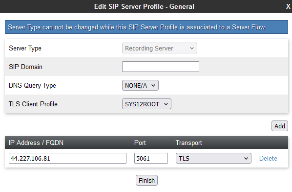
On the Edit Server Configuration Profile window, in the Server Type field, click Recording Server.
-
For TLS Client Profile, select the client profile you created in Configure the TLS.
-
In the IP Address / FQDN field, type the IP address of the NiCE CXone AudioCodes SBC server.
-
In the Port field, enter 5061 for a secure TLS connection, or 5065 for a mutual TLS (mTLS) connection.
-
In the Transport field, select TLS transport protocol.
-
Click Next.
-
On the Add Server Configuration — Advanced page, to select the interworking profile, perform one of these:
-
In the Interworking Profile field, select the avaya-ru profile.
The avaya-ru profile is the default interworking profile.
-
Clone the default avaya-ru interworking profile and select the cloned interworking profile.
-
-
Verify that the Enable Grooming check box is selected.
For a recording server, the system selects the Enable Grooming field by default. Do not clear the Enable Grooming check box.
-
Click Finish.
Create a Routing Profile
A new routing profile must be created for the Recording Server. Routing profiles define a specific set of packet routing criteria that are used in conjunction with other types of domain policies. Routing profiles identify a particular call flow and thereby ascertain which security features are applied to those packets. The parameters defined by routing profiles include packet transport settings, name server addresses and resolution methods, next hop routing information, and packet transport types.
To create a routing profile:
-
Log in to the EMS Web interface with administrator credentials.
-
In the navigation pane, select Configuration Profiles > Routing. The Application pane displays the existing routing profiles. The Content Area displays the routing rules comprising a selected routing profile.
-
In the Application pane, click Add.
-
Type a distinctive name for the new routing profile, and click Next.
-
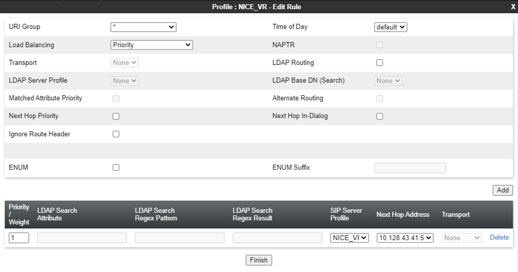
Enter the requested information in the appropriate fields, which are described in the table below.
To use alternate routing, ensure that you set the Trans Expire field on the Timers tab from Global Profiles > Server Interworking to an appropriate short duration. Any request sent from the server times out if a response is not received within the time set as the transaction expiration timer. Therefore, alternate routing does not work if the Trans Expire field is set to the default value of 32 seconds.
Field Name
Description
URI Group Indicates the URI Group to which the next hop routing profile applies. The possible values are:
-
*
-
Emergency
Time of Day Indicates the time of day for the trunk server to resolve the routing profile.
For remote users, do not use the Time of Day field to resolve the routing profile.
Load Balancing Indicates the type of load balancing option.
Leave the default value.
Transport Indicates the next hop address that you must configure. Alternatively, select the transport type. The system uses the routing profile transport type to route the message. Next Hop In-Dialog Indicates the Next Hop configuration for the In-Dialog message. If you enable the Next Hop In-Dialog option, the In-Dialog request will try to use the same routing entry to route the message. NAPTR Indicates whether Naming Authority Pointer is activated or deactivated. When you select the Load Balancing algorithm as DNS/SRV, the system enables the NAPTR check box. If you disable NAPTR, you must specify the transport protocol. Next Hop Priority Indicates whether in cases when the SBC fails to route a message using the resolved routing entry from the message, that is, using the request URI or Route Header, the system will send the message to the alternate routing entry from the routing profile. Ignore Router Header Indicates whether Avaya SBCE will ignore the Route Header. ENUM Indicates whether the support for the E.164 Number Mapping (ENUM) protocol is enabled. ENUM Suffix Indicates the ENUM suffix that is added to change the number to a domain name.
This field is available only when you select the ENUM check box.
Add Adds a next hop address. Priority / Weight Indicates the priority and weight assigned for load balancing options.
Leave the default value.
Server Configuration Indicates the server configuration. Next Hop Address Indicates the IP address or domain of the Next Hop server. You can add up to 20 next hop addresses. Transport Indicates the transport type for each next hop address. Select the protocol for transporting outgoing signaling packets.
The supported options are:
-
None
-
TCP
-
UDP
In this case, the Common Transport Type field is unavailable. You can select the transport type according to the next hop address.
-
-
Click Finish. The Application pane displays the new Routing profile.
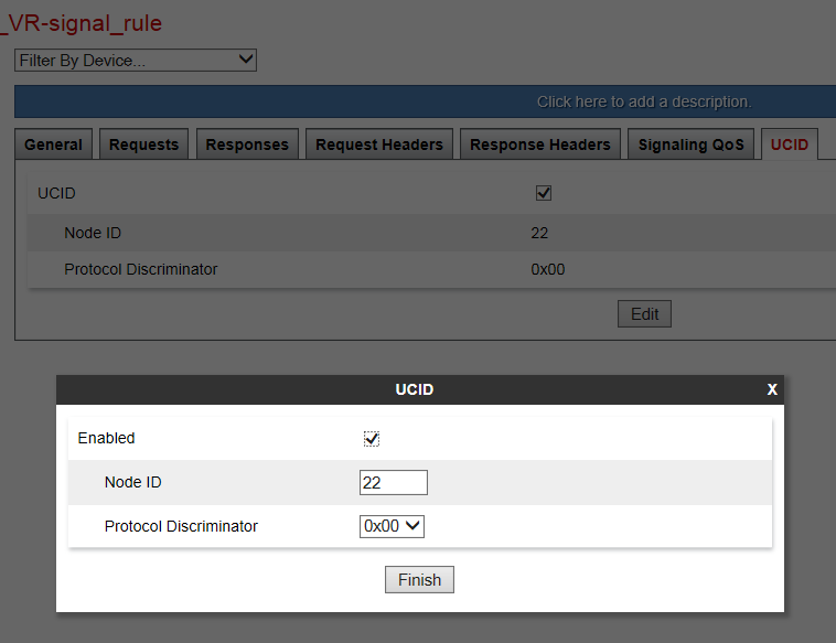
Enable UCID
UCID must be enabled for the signaling rules used on the Session Manager endpoint policy group content.
To enable UCID:
-
Log in to the EMS Web interface with administrator credentials.
-
In the left navigation pane, select Domain Policies > Signaling Rules. The left Application pane displays the existing Signaling Rule sets, and the Content pane displays the parameters of the selected Signaling Rule set.
-
Click the Signaling Rule that Avaya SBCE must use for the Session Manager.
-
Click the UCID tab.
-
Click Edit.
-
Select the UCID check box to enable it.
-
In the Node ID field, enter a node ID. Every entity that generates a UCID has a node ID. The node ID must be unique across a solution.
-
In the Protocol Discriminator field, click 0x00. The protocol discriminator configured on Avaya SBCE must match the value configured for Communication Manager. If the Communication Manager CTI application requires the protocol discriminator 0x04 for the legacy Interaction Center application, you can set the protocol discriminator to 0x04.
-
Click Finish.
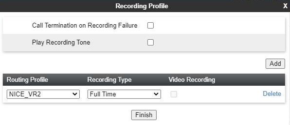
Create a Recording Profile
To create a recording profile:
-
Log in to the EMS Web interface with administrator credentials.
-
In the left navigation pane, select Configuration Profiles > Recording Profile.
-
Click Add in the Recording Profiles section to add a new recording profile.
-
Select the required Routing Profile.
-
Select Full Time as the Recording Type.
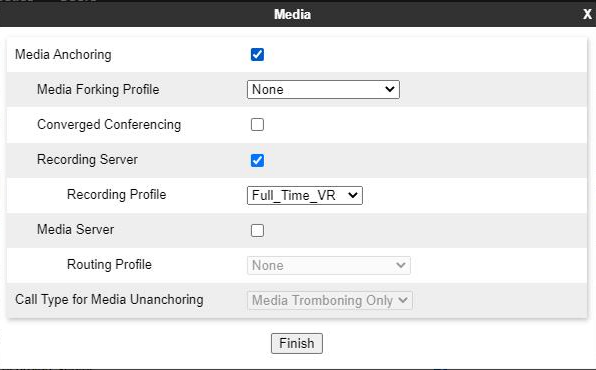
Create a Session Policy
A recording type and a routing profile must be assigned by creating a new session policy for the Recording Server.
To create a session policy for a Recording Server:
-
Log in to the EMS Web interface with administrator credentials.
-
In the left navigation pane, select Domain Policies > Session Policies. The left Application pane displays the existing session policies, and the Content pane displays the parameters of the selected session policy.
-
In the Applications pane, click Add.
-
In the Session Policy window, in the Policy Name field, type a name for the new session policy, and click Next. The second Session Policy window is displayed.
-
Select the Media Anchoring check box.
-
Select the Recording Server check box.
-
Select the Recording Profile that has been created in Create a Recording Profile.
The Routing Profile is assigned to the Recording Profile.
-
In the Recording Type field, select the type of recording required. The available options are Full Time and Selective.
-
(Optional) To play a tone to indicate that the call is being recorded, select the Play Recording Tone check box.
The default recording tone is the CALL_CONNECTING wave file. If required, you can replace the default tone with a new, short duration wave file.
-
(Optional) To configure Avaya SBCE to terminate the session when the Recording Servers do not respond, select the Call Termination on Recording Failure check box.
-
In the Routing Profile field, select the routing profile that Avaya SBCE must use for the Recording Server.
-
Click Finish.
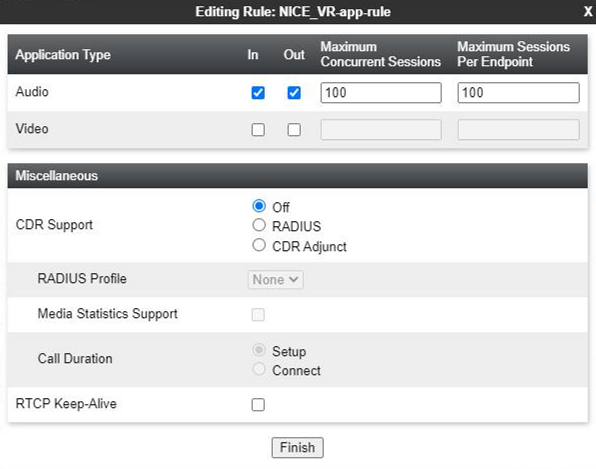
Create an Application Rule
A new application rule must be created for the Recording Server. Application rules define the type of SBC-based Unified Communications (UC) applications that Avaya SBCE protects. You can also specify the maximum number of concurrent voice and video sessions that your network can process before resource exhaustion. Application Rules are part of the Endpoint Policy Group configuration. A customized application rule or the default application rule can be selected from a list during the configuration while creating an Endpoint Policy group.
The Application Rules function is available in the Domain Policies menu.
Avaya provides a default application rule set named default. Do not edit this rule, because improper configuration might cause subsequent calls to fail.
To configure an Application Rule for a Recording Server:
-
Log in to the EMS Web interface with administrator credentials.
-
In the left navigation pane, select Domain Policies > Application Rules. The left application pane displays the existing Application Rule sets, and the content pane displays the parameters comprising the selected Application Rule set.
-
In the left Applications Rules pane, click Add.
-
In the Application Rule window, enter a name for the new Application Rule and click Next. The second Application Rule window is displayed.
-
Enter the requested information in the fields which are described in below.
Field Name
Description
Application Type Indicates the type of SIP application for which this Application Rule is being configured. The possible values are:
-
Audio
-
Video
In Indicates whether the application rule applies to the audio and video traffic entering the enterprise network.
Out Indicates whether the application rule applies to the audio and video traffic originating from within the enterprise network.
Maximum Concurrent Sessions Indicates the maximum number of concurrent application sessions that can be active for the selected application type. Additional application requests are blocked when this threshold is exceeded. Maximum Sessions Per Endpoint Indicates the maximum number of application sessions that can be active for an endpoint. Additional application requests are blocked when this threshold is exceeded. CDR Support Indicates the type of support for call detail records (CDR). The possible values are:
-
None: No call detail records are not provided.
-
With RTP: Call detail records with call quality and call statistics are provided in addition to the changes in call states.
-
Without RTP: Call detail records with only the changes in call states are provided.
RTCP Keep-Alive Indicates whether the RTCP Keep-Alive feature is enabled. -
-
Click Finish to save, then exit, and return to the Application Rules page.
Create a Media Rule
A new media rule must be created for the Recording Server. For SRTP calls, verify that interworking is enabled.
To create a media rule for a Recording Server:
-
Log in to the EMS Web interface with administrator credentials.
-
In the left navigation pane, select Domain Policies > Media Rules. The Applications pane displays the existing Media Rule sets, and the Content pane displays the parameters for the selected Media Rule set.
-
In the left Applications Rules pane, click Add.
-
In the Media Rule window, enter a name for the new Media Rule.
-
Click Next.
-
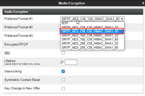
On the Audio Encryption tab, under the Audio Encryption area, click the dropdown and select:
-
SRTP_AES_CM_128_HMAC_SHA1_80 cipher for Preferred Format #1.
-
SRTP_AES_CM_128HMAC_SHA1_32 cipher for Preferred Format #2.
-
NONE for Preferred Format #3.
-
-
Click Next.
-
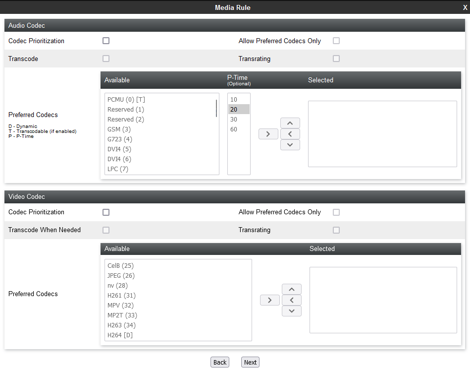
Real-Time Third Party Telephony Recording (Multi-ACD) SIPREC supports only the G711A, G711U, G729 and G729A audio codecs. The NiCE CXone AudioCodes SBC will reject the offer if there is no matching codec in the SDP offer. In the Audio Codec section, select the Codec Prioritization check box and select the supported codecs as the preferred codecs.
-
(Optional) Select the Allow Preferred Codecs Only check box.
-
(Optional) If you require media transcoding, select the Transcode check box.
For transcoded calls, you must configure the transcoded codec G711 or set the codec prioritization as G711MU. For SIPREC, one side of the call is transcoded, and the other side must be on G711 or vice versa. Media can be streamed to the Recorder on the G711 codec.
-
(Optional) In the Available column, select the preferred audio and DTMF dynamic codecs that the recorder supports, and click >.
-
(Optional) If the recording tone is enabled, select the telephone-event and G729 preferred codecs.
-
Click Next.
-
(Optional) Enable BFCP, FECC, and ANAT if required.
-
Click Finish.
Create an Endpoint Policy Group
A new endpoint policy group must be created for the Recording Server.
Avaya provides a default Signaling Rule set named default. Do not edit this rule set, because improper configuration might cause subsequent calls to fail.
To create an endpoint policy group for a Recording Server:
-
Log in to the EMS Web interface with administrator credentials.
-
In the left navigation pane, select Domain Policies > End Point Policy Groups. The Application pane displays the defined policy groups, and the Content pane displays the parameters of the selected policy group.
At least one Security Rule set must be defined before a policy group can be created. If you do not create a security rule, Avaya SBCE displays a prompt to create such a rule.
-
In the left Application pane, click Add. The Policy Group window is displayed.
-
In the Group Name field, type a name for the new endpoint policy group, and click Next. The system displays the second Policy Group window, where you must set the policy group parameters.
-
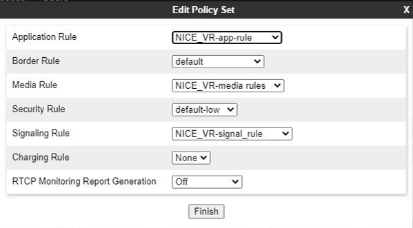
Enter the relevant parameters, and click Finish. The Application pane displays the newly created endpoint policy group. When you click the endpoint policy group, the system displays the details in the Content pane. The endpoint policy group fields are described below.
Field Name
Description
Group Name Indicates the name of the endpoint policy group.
Application Rule Indicates the application rule that will determine which applications use this policy group.
Border Rule Indicates the border rule that will determine which applications will use this policy group.
Media Rule Indicates the media rule that will be used to match media packets. Security Rule Indicates the security rule that will determine which Avaya SBCE security policies will be applied when this policy group is activated. Signaling Rule Indicates the Signaling Rule that will be used to match SIP signaling packets.
-
Click Finish.
Add a Session Flow
A session flow for the Recording Server must be added.
If you have a hairpin between a remote worker and a trunk, you must create three session flows:
-
Session Flow 1 between the trunk and Session Manager1.
-
Session Flow 2 between Session Manager2 and the remote worker.
-
Session Flow 3 for hairpin flow between the trunk and the remote worker.
To add a session flow:
-
Verify that you have provisioned enough RTC ports for the media interface in the direction of the enterprise network.
For example, if you require 1000 ports for calls, you must provision 2000 ports for RTP-used even ports and RTCP-used odd ports. To add SIPREC, you must provision another 4000 ports inside and outside RTP to the NiCE CXone AudioCodes SBC server.
-
Log in to the EMS Web interface with administrator credentials.
-
In the left navigation pane, select Network & Flows > Session Flows.
-
In the Application pane, click the Avaya SBCE device for which you want to create a new session flow. The Content Area displays the session flows currently defined for that Avaya SBCE device.
-
Click Add.
-
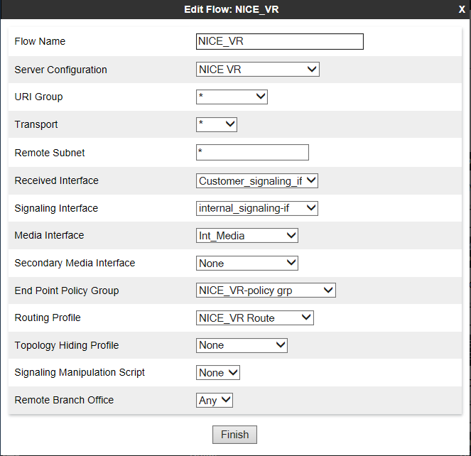
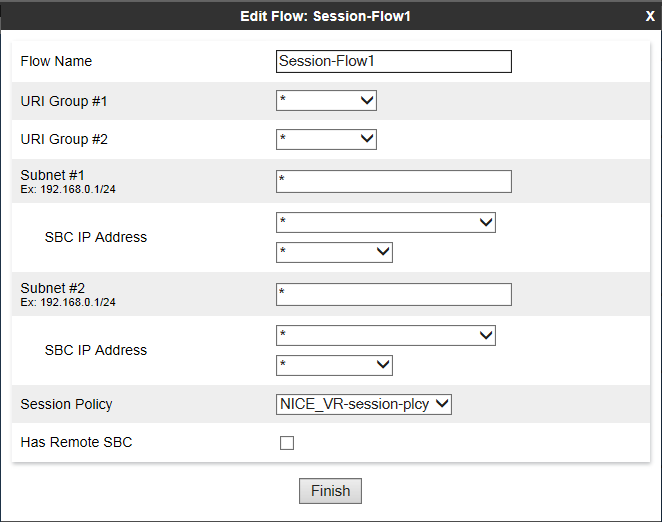
In the Edit Flow window, in the Flow Name field, type the name of the session flow.
-
For the URI Group #1 and URI Group # 2 fields, choose one of these options:
-
Select the URI group policy that will be used to identify the source or destination of the call and to restrict the calls recorded by Avaya SBCE.
-
Leave the default value * to record all calls.
-
-
For the Subnet #1 and Subnet #2 fields, choose one of these options:
-
Type the subnet addresses. You can specify the source and destination subnet addresses.
-
Leave the default value * to record all calls.
-
-
In the SBC IP Address field, select the network name (host name) and IP address of the Avaya SBCE.
-
In the Session Policy field, select the session policy that you created for the Recording Server in Create a Session Policy.
-
Click Finish.
Create a Server Flow
A server flow must be created for each Recording Server.
For a remote worker configuration, create a server flow for a remote worker. Verify that the remote worker A1 interface is set as the received interface and that the Avaya SBCE interface towards the recorder is set as the signaling interface for the server flow.
To create a new server flow manually:
-
Log in to the EMS Web interface with administrator credentials.
-
In the left Navigation pane, navigate to Network & Flows >End Point Flows.
-
The Application pane lists the registered Avaya SBCE security devices to which the new flow will be applied. The content area displays a specifically ordered list of Subscriber or Server call flows for the selected Avaya SBCE security devices.
-
From the Application pane, select the Avaya SBCE device for which the new Server End-Point Flow is being created. The system displays the End-Point Flows screen, showing the flows that are currently defined for that Avaya SBCE.
-
Click the Server Flows tab.
-
Click Add.
-
In the Edit Flow window, enter the information in the fields.
-
Click Finish.